A quick guide to taking full advantage of designing your substation in RatedPower.
RatedPower offers two ways to design the basic engineering of the step-up substation of your PV plant, either automatically or manually by defining a few related parameters. In a few minutes, you will have a complete single-line diagram and a fully detailed report. Each substation's component is calculated based on the project characteristics while fulfilling the requirements of the international electrotechnical commission (IEC) standards or IEEE standards upon your choice.
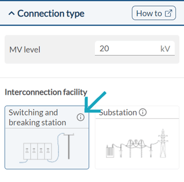
Switching and breaking station
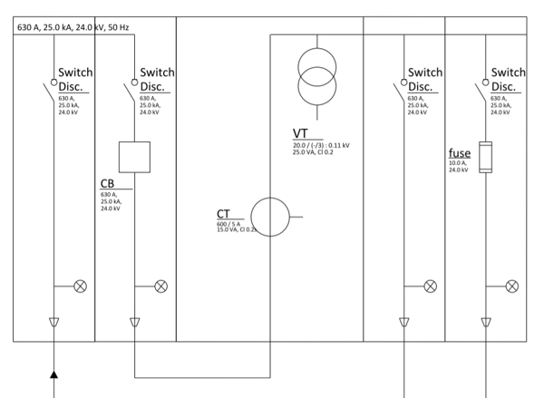
The switching and breaking station or sectioning station consists of a number of cubicles that allow for a modular design. Such modularity provides the ability to extend and adapt the station to the development of the network and to replace the modules without interrupting the supply. Each module will include different protection or measurement devices depending on the type of cubicle.
Switching and breaking stations in general have several cubicles designed for a feeder function and other cubicles designed for measurement and protection purposes. The metering cubicles measure the operating voltage and current levels (metering function). The protection cubicles safeguard the station against overvoltage events or faults (circuit breaker or fuse protection function).
When should I use this switching and breaking station?
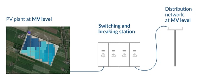
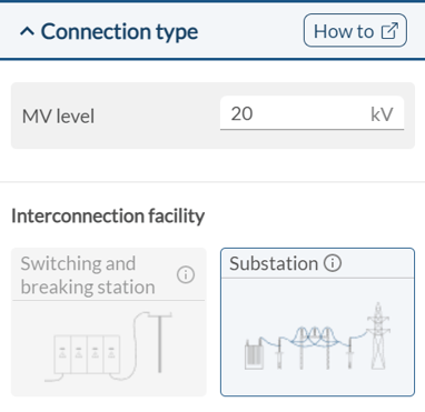
The switching and breaking station is the perfect solution to connect the PV plant to medium voltage (MV) distribution grids when it is not necessary to install step-up power transformers. In this case, the station and the PV plant will operate at the same MV level as the distribution grid.
The voltage level of the distribution grid depends on local parameters, but it is common to use a switching and breaking station when the interconnection level is somewhere between 24 and 36 kV.
Can't use the switching and breaking station option. How do I enable it?
There are three conditions required in order to enable the switching and breaking station option:
-
The installed capacity of the PV plant + BESS must be lower than 100 MVA.
-
The total current of the PV plant + BESS must be lower than 2100 A. You can calculate the total current of your PV plant by:
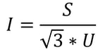
Where: I is the current of your PV plant + BESS [A], S is the capacity of the power plant+ BESS [VA], and U is the medium voltage level [V].
- The medium voltage level is lower than or equal to 50 kV.
In the table below, the approximate limits of installed capacity per medium voltage system with the option of a switching and breaking station are shown.
| Medium voltage system | Installed capacity |
| 11.5 kV | Up to 24.5 MVA |
| 16 kV | Up to 34.5 MVA |
| 20 kV | Up to 43 MVA |
| 24 kV | Up to 51.5 MVA |
| 30 kV | Up to 100 MVA |
| 36 kV | Up to 100 MVA |
| 45 kV | Up to 100 MVA |
My PV plant fulfills all requirements, so why is the switching and breaking station still disabled?
In some cases, despite the PV plant fulfilling the three requirements, the switching and breaking station's option won't be enabled. In general, this happens when the perimeter of the PV plant is irregular or rotated with respect to the north-south direction, and the total current of the plant is close to 2100 A.
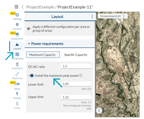
This only happens when the maximum capacity is selected under power requirements. When you choose the maximum capacity option, RatedPower cannot figure out the exact installed capacity. What it does instead is estimate the power capacity based on the type of structure, the pitch distance, and the total area. This estimation causes the switching and breaking station option to be disabled despite the requirements being fulfilled.
 Don't worry though, there is a simple solution for this!
Just go to the Layout tab (Power requirements), select Specific Capacity, and introduce the number of inverters you need in your PV plant.
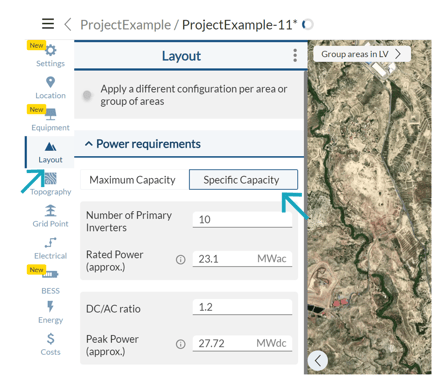
This way, RatedPower can know the exact installed capacity of your PV plant, and the switching and breaking station option is thus enabled!
Substation
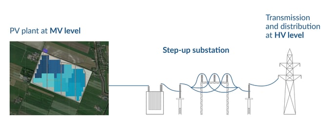
To connect a solar PV plant to distribution or transmission networks (46 - 550 kV), it is necessary to step up the voltage level from medium to high voltage. The purpose of a substation is to convert low voltages to high voltages, or vice versa, using power transformers.
An important decision that is made at the planning/concept stage is the type of equipment that will be used for the substation. Three typical types of equipment are:
- Air-insulated switchgear (AIS)
- Gas-insulated switchgear (GIS)
- Mixed-technology switchgear (MTS)
At this moment, RatedPower solution will define an air-insulated substation (AIS).
In addition, RatedPower, by default, will automatically choose the type of substation´s arrangement between the following ones:
- Line-to-transformer. The line-to-transformer substation connects the PV plant to the grid directly without the use of a busbar. It stands out for being the simplest substation layout.
- Single busbar. A single busbar is established to allow operational and flexible bay configurations.
- Double busbar. Two busbars are established to allow operational and flexible bay configurations, to increase the security of supply, and to improve availability during maintenance periods.
Nonetheless, the user can still decide to manually select the type of arrangement.
When should I use a substation?
The substation is used to connect the PV plant to high-voltage distribution or transmission grids. The voltage level of the PV plant will be stepped up to a high voltage level to facilitate the transport of the electric current.
The preferred high voltage level of distribution and transmission networks will depend on the country of the project. Nonetheless, it is common to use a substation when the interconnection level is somewhere between 46 kV and 550 kV.
When I choose the substation, how can I know the type of arrangement?
You have the possibility to manually choose between a single busbar or a double busbar substation arrangement.
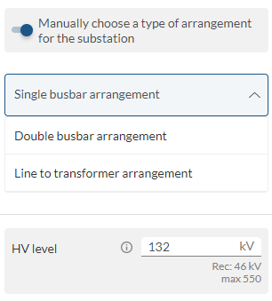
However, there is an option that automatically defines the substation arrangement. But, how do you know what arrangement is chosen by RatedPower?
The substation arrangement will depend on several criteria such as the admissible and short-circuit currents that could flow per each potential transformer bay, the short-circuit impedance of the power transformers, and the current-carrying capacity of the cables.
A simple estimation can be carried out to find out the type of arrangement. We refer to this as our "2500 A method".
This method serves as an approximation but can still give us a quick idea of what type of arrangement we have. Let's consider the following voltage level, installed capacities, and resulting current levels.
| MV Level | 20 kV | 20 kV | 20 kV |
| Installed Capacity | 80 MVA | 100 MVA | 275 MVA |
| Total current | 2300 A < 2500 A | 2500 A < 2880 A < 3 * 2500 A | 3 * 2500 A < 7930 A |
| Type of arrangement | Line-to-transformer | Single Busbar | Double busbar |
In order to compute the total current, here is an example for the 80 MVA PV plant:
80 MVA * 10^6 / (20 kV * 10^3 * √3) = 2300 A
Summary
Can't remember all these details, just keep the following things in mind:
- You can size the interconnection facility according to the IEC or the IEEE standard.
- Use the switching and breaking station when the PV plant is interconnected to MV distribution networks up to 45 kV.
- To enable the switching and breaking station, the installed capacity of the PV plant + BESS must be lower than 100 MVA, its total current must be lower than 2100 A, and medium voltages lower or equal to 50 kV.
- If the switching and breaking option is disabled despite fulfilling the requirements above, go to Electrical → Power Requirements and define a Specific Capacity instead of using the Maximum Capacity option.
- Connect your PV plant to HV distribution or transmission networks from 46 kV to 550 kV by selecting the substation.
- Finally, the arrangement of the substation is automatically defined most optimally. However, to have an idea of your substation's arrangement, apply our so-called "2500 A method".
For any other questions or more information regarding this topic, you can contact us at: support@ratedpower.com