This article explains how RatedPower's cabling topology works
Introduction
RatedPower's cabling topology aims to reduce the total cable length inside the PV plant. This article explains how this goal is achieved.
LV system topology
String wiring
In RatedPower, modules are connected in series following a leapfrog configuration as shown in the image below. This connection allows the positive and negative cables to have the same length, which reduces the total length of the string cables.
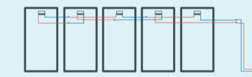
Note: The length shown in the BOQ that RatedPower generates considers both the positive and negative cables.
String definition and positioning within a structure
In RatedPower, a string is represented by a block of modules defined by the user through the number of modules per string parameter. For example, a two-row portrait/vertical (2P) tracker with a configuration of 2 strings and a number of modules per string of 20 is going to have 40 modules per structure in total.
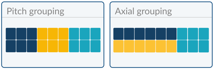
 There are two types of string positions within a structure. Pitch grouping configures strings to be formed favoring the connection of the modules in the pitch direction. Axial grouping contrarily groups the cables based on the connection of the modules in the axial direction.
 Combiner box/string inverter location
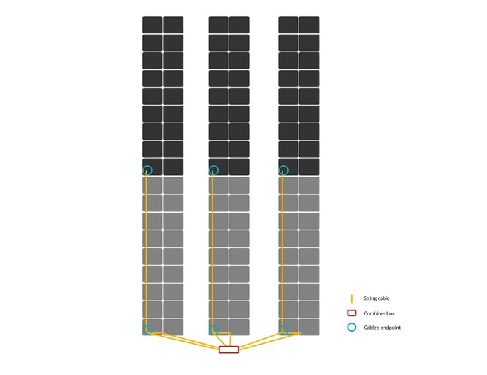
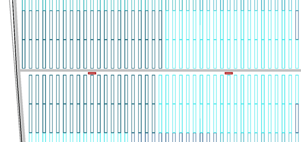
Before placing the combiner box or string inverters, RatedPower determines which structures share combiner box/string inverters. Within that group of structures, the software analyses which structure is positioned best to reduce the length of used string wire (i.e. the structure that is positioned in the center of the structure group). If there is more than one at the same distance from the center of the group, the one closest to the power station is chosen.
The groups of structures that are close to each other are subsequently re-evaluated to see whether the string boxes for both groups of structures can be positioned such that the cables are also aligned. If there is indeed a structure in position to decrease the cable length, the box (and inherently the cable) is relocated to follow a nearby trench. Once the optimal structure is chosen, the string box is located at the edge of the structure that is most centered with respect to its cluster.
DC Harness
The DC harness configuration collects strings from the same table, a constraint to this grouping however is that the harness over the number of strings per table should be an integer result.
For example, if there are six strings per table (2P) connected in pitch grouping you can collect them in four different ways:
- You can combine all six strings, having in total 1 harness.
- You combine three strings, having in total 2 harnesses.
- You combine two strings, having in total 3 harnesses.
- You can separate all strings, resulting in no DC harness.
The DC harness must be straight and parallel to the axis of the structure. Due to this, a "Pitch grouping" configuration generally allows more strings to be connected to a DC harness than an "Axial grouping" configuration.
For the above example (six strings per table (2P)) if we change to "Axial grouping" the six strings/harness (having in total 1 harness/structure) option would not be available, as a single straight cable is not able to collect all the strings, we would need at least two harnesses.
In summary, for "Pitch grouping" the string collection per harness has to be a number of strings divisible by the number of strings per table. For "Axial grouping" this number must be a number of strings divisible by the number of strings per table divided by the number of "rows" within a table.
Direct current (DC) Bus
RatedPower offers the option for DC bus system configuration. This setup enables the user to define the number of string cables or harness (from different tables) which are connected to one point at the DC bus for the corresponding power station.
MV system topology
RatedPower's algorithm locates the power stations at the center of their corresponding block of structures with the objective of minimizing the length of the low voltage (LV) cables.
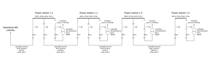
The power stations are accordingly connected using a radial configuration. This results in a lower cost of cabling and more simplicity in the design. The following image illustrates this radial configuration:
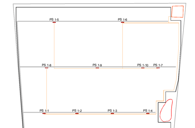
The software automatically connects power stations together based on their capacity and proximity. Each MV cable will collect power stations until the total load current set by the user in the grid point tab is reached.
If you would like to review more information regarding the electrical configuration in RatedPower (from defining the number of modules per string all way to the power stations), please refer to the article How to define your electrical configuration.
Trenches
LV trenches
The LV trenches will drive the LV cables from the combiner boxes/string inverters to the power stations. These may vary depending on the chosen road layout.
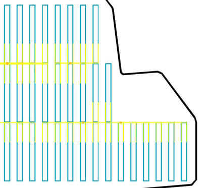
In the case of horizontal roads, the LV trenches will first be installed horizontally following the edges of the structures and then vertically to reach the power stations (below trackers), which can be seen in the image below.
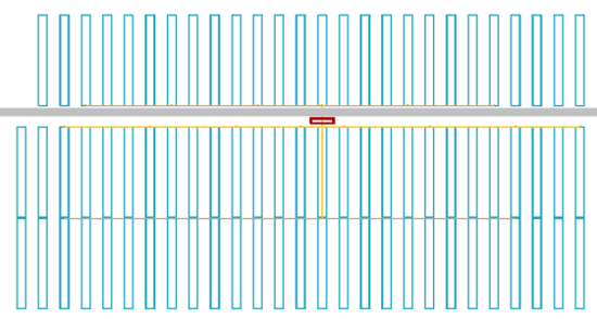
As for the case of vertical road layout, the LV trenches will first be installed vertically and then horizontally to reach the power stations (both, vertical and horizontal trenches will be installed below trackers).
Note: For fixed structures, the trenches are installed in a similar way but in the case of horizontal roads, all the trenches are below the structures, and for the vertical roads, only the horizontal trenching will be below.
Keep in mind that when the uniform arrangement option is selected, LV trenching will be defined in a regular grid. Alternatively, when border adaptation is selected, LV trenching will be tangled and less uniform.

Medium voltage (MV) trenches
Power stations are connected together through MV trenches. These are usually installed following the roads. If the power stations are separated by the DC field, the MV trenching will cross the field without crossing or going below the structures.
Summary
In conclusion, RatedPower's algorithm tends to group the structures in a way that minimizes the cables' length. This objective results in connecting and placing the electrical elements in the way mentioned above.
The software uses leapfrog to connect the positive and negative module wires, it places the combiner boxes either at the edge of the structure. Moreover, the software uses a radial configuration to connect the power stations and installs the LV and MV trenches depending on the road layout and the structure type.
For any other questions or more information regarding this topic, you can contact us at support@ratedpower.com