Do you want to include a distributed battery storage system in your PV plant? Design your hybrid PV + DC-coupled BESS plant in RatedPower.
Introduction
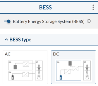
It is currently possible to hybridize your PV plant by including a DC-coupled BESS system. In the BESS tab, by activating the DC-Coupled BESS option, you will be able to select the main equipment and electrical parameters of the system to get it included in the final layout of the PV plant.
How to include a DC-Coupled BESS
As the DC-Coupled BESS will be distributed along the PV plant, no extra requirements on the site are needed. Even so, if a battery area (BA) is included in our site to eventually evaluate an AC-Coupled system, the first step will be to select ‘’DC-Coupled BESS’’ inside the BESS tab.
If no BA area is included, just by activating the BESS option inside the BESS tab, we will have the possibility to include the system in our PV plant.
Main equipment definition
The DC-Coupled BESS option will only be enable inside the Design Process if the user has selected central inverters in the Equipment tab.
Only primary inverters from the main Power Station (PS) will have the option to connect a DC-Coupled BESS. If main PSs also have secondary inverters, those inverters won’t have storage. The primary inverters of the secondary PSs won’t have DC/DC converters neither.
Once the central inverter is selected, the main equipment to be defined inside the BESS tab are the battery containers and the DC/DC converters.
- DC/DC converters: The DC/DC converters (buck/boost converter) change the battery voltage to the inverter input voltage (equivalent to the string voltage of the PV plant).
As a user, you will have the possibility to manually define the DC/DC converter power, and this value will be limited to a maximum of 1.5*Power of the inverter.
Once the maximum continuous power of each DC/DC converter has been set, the user can define the number of converters connected to one central inverter (this must be an integer number).
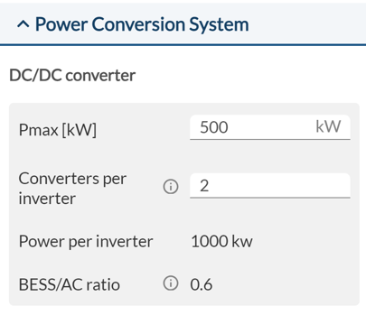
The interface will show the total DC/DC converter power per inverter and the BESS/AC Power Ratio.
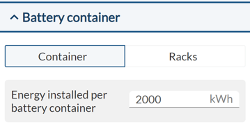
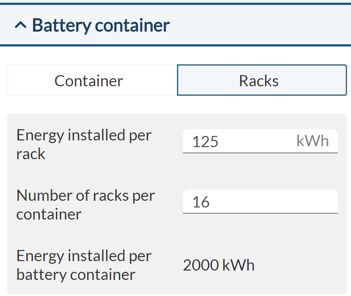
- Battery containers: in RatedPower, it is assumed that the storage solution is modular. As a user, you will set the capacity of a battery container. Alternatively, you can set the capacity of a single battery rack and the number of racks to be included per container.
Once you have defined the number of DC/DC converters per inverter and the battery containers' capacity, next step will be to set the whole system capacity.
BESS capacity and supply duration
Having established the battery containers' capacity and the quantity of DC/DC converters per inverter, the subsequent step involves defining the system capacity along with the duration of supply.
In the context of system capacity, you'll have the possibility to choice between two different options: specific capacity or maximum capacity.
- BESS Specific capacity (option 1): as a user, you will be able to establish the desired quantity of main power stations (PS) with battery containers connected to it. This definition is done by defining the “Number of PS with storage” (integer number).
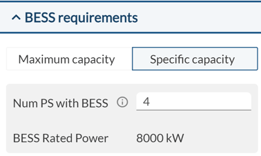
Remember that only the primary inverters of these power stations will have storage or DC-DC converters. These power stations will follow the setup called "Main Power Station" in the Equipment section. Any other power station types (secondary PSs) won't be able to have storage or DC-DC converters.
As a result, the interface will show the user the total BESS discharge power.
- BESS Maximum capacity (option 2): By default, all primary inverters of the main power stations will have storage and DC-DC converters. These power stations will follow the specifications of the "Main Power Station" configuration within the Equipment tab.
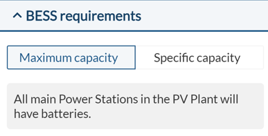
As before, it's not an option for secondary power stations to be equipped with storage or DC-DC converters. However, these secondary power stations can be utilized to maximize your installed capacity.
As a result, the interface will show the user the total Approx. BESS discharge power.
- BESS Supply duration: this step involves determining the number of battery containers desired for each power station (PS). You'll have the flexibility to choose up to a maximum of 6 containers per PS. By default, the software will preselect 1 container per PS.
This will be setup by specifying the "Minimum supply cycle duration" in hours from the dropdown menu.
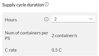
As a result, the interface will show the total number of battery containers per PS with storage and the maximum C-rate in [1/hours]
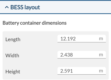
BESS dimensions and distances
To adjust the real BESS solution into the PV plant layout, you will have the possibility to define the dimensions of the battery containers inside the last section of the BESS tab.
The spacing between equipment holds significant importance for BESS, as it must align with requirements set forth by different standards.
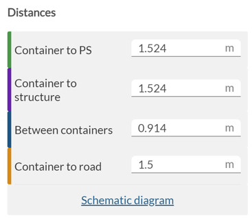
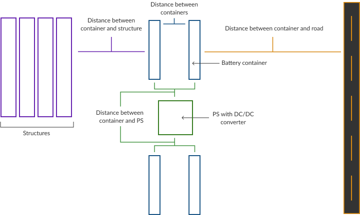
Within this layout section (inside the BESS tab), you will also have the option to establish four different setbacks. These setbacks serve to ensure compliance with the standards' stipulated requirements.
- Power Station (PS) to Battery Container: This distance must be greater than 5 feet (1.524 m) according to the NFPA 855 standard. A maximum value of 15 feet (4.572 m) can be defined.
- Distance between Battery Containers (only if more than 2 battery containers per PS): The distance between Battery Containers must be greater than 3 feet (0.9144 m) according to the NFPA 855 standard. A maximum value of 15 feet (4.572 m) can be defined.
- Battery Container to structure: This distance must be greater than 5 feet (1.524 m) according to the NFPA 855 standard. maximum value of 15 feet (4.572 m) can be defined.
- Battery Container to road: It is possible to manually define the distance of the Battery container to the road. The same value limits will be considered for setbacks as those currently considered for Power Stations. A minimum of 1.5 meters and a maximum of 100 meters can be set.