A quick guide to take full advantage of designing the interconnection facilities in RatedPower.
This article explains what are the different interconnection facilities available in RatedPower and how to customize them.
- If you want to learn more about the different interconnection schemas you can define connecting these facilities, give a look to this article.
- In our Interconnection Facility Methodology, you can find detailed information on how we size and calculate the substation.
RatedPower offers two ways to design the basic engineering of the interconnection facilities of your PV plant, either automatically or manually by defining a few related parameters. In a few minutes, you will have a complete single-line diagram and a fully detailed report. Each component of the interconnection facility is calculated based on the project characteristics while fulfilling the requirements of the international electrotechnical commission (IEC) standards or IEEE standards upon your choice.
In this article, we will provide further details on the three types of interconnection facility that you can define in RatedPower:
- Switching and breaking station (SBS)
- Substation (ST)
- Pooling Substation (ST)
- The main difference between a SBS and a ST is that a SBS doesn't include a power transformer to step-up the voltage.
- The main difference between a substation and a pooling substation is that a substation has incoming MV lines while a pooling substation has incoming HV lines.
Switching and breaking station (SBS)
A switching and breaking station or sectioning station consists of a number of cubicles that allow for a modular design. Such modularity provides the ability to extend and adapt the station to the development of the network and to replace the modules without interrupting the supply. Each module will include different protection or measurement devices depending on the type of cubicle. A SBS is used to collect the power from different MV lines (feeders) coming from the power stations (PS) on the field reducing the number of outgoing lines.
The outgoing line can be connected directly to the grid or to a substation depending on the interconnection schema.
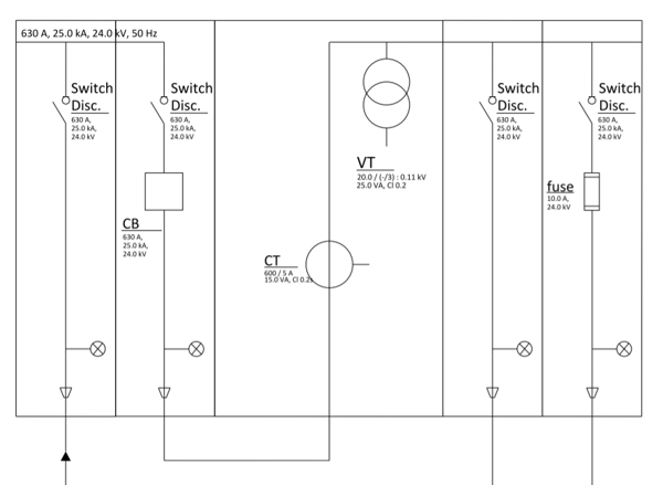
Switching and breaking stations in general have several cubicles designed for a feeder function and other cubicles designed for measurement and protection purposes. The metering cubicles measure the operating voltage and current levels (metering function). The protection cubicles safeguard the station against overvoltage events or faults (circuit breaker or fuse protection function).
To use a SBS you'll need to define a SBS polygon inside your site. RatedPower will then automatically define and draw one or more SBS containers inside that area as in the following example.

RatedPower determines the number of containers based on the following rules:
-
The total power of each container must be lower than 100 MVA.
-
The total current of each container must be lower than 2100 A. You can calculate the total current by:

Where: S is the sum of the power of the MV lines connected to the container [VA], and U is the medium voltage level [V].
- The medium voltage level is lower than or equal to 45kV
In the table below, the approximate limits of capacity of a single SBS container are shown.
| Medium voltage system | Installed capacity |
| 11.5 kV | Up to 24.5 MVA |
| 16 kV | Up to 34.5 MVA |
| 20 kV | Up to 43 MVA |
| 24 kV | Up to 51.5 MVA |
| 30 kV | Up to 100 MVA |
| 36 kV | Up to 100 MVA |
| 45 kV | Up to 100 MVA |
Substation (ST)
This interconnection facility is used to step up the voltage from the level used on the field (determined by the power stations' transformers) to a higher level, using power transformers.
An important decision that is made at the planning/concept stage is the type of equipment that will be used for the substation. Three typical types of equipment are:
- Air-insulated switchgear (AIS)
- Gas-insulated switchgear (GIS)
- Mixed-technology switchgear (MTS)
At this moment, RatedPower solution will define an air-insulated substation (AIS).
For each substation, RatedPower will automatically determine, be default, the following elements:
- Substation arrangement
- Transformer type
- Transformer bay size
- Output bays (only for highest voltage level facility)
Each of them can also be selected manually by the user, let's look into details of each option.
Substation arrangement
The types of substation's arrangement you can choose from are:
- Line-to-transformer. The line-to-transformer substation connects the PV plant to the grid directly without the use of a busbar. It stands out for being the simplest substation layout.
- Single busbar. A single busbar is established to allow operational and flexible bay configurations.
- Double busbar. Two busbars are established to allow operational and flexible bay configurations, to increase the security of supply, and to improve availability during maintenance periods.
 The automatic substation arrangement selection, on the other hand, depends on several criteria such as the admissible and short-circuit currents that could flow per each potential transformer bay, the short-circuit impedance of the power transformers, and the current-carrying capacity of the cables.
A simple estimation can be carried out to find out the type of arrangement. We refer to this as our "2500 A method".
This method serves as an approximation but can still give us a quick idea of what type of arrangement we have. Let's consider the following voltage level, installed capacities, and resulting current levels.
| MV Level | 20 kV | 20 kV | 20 kV |
| Installed Capacity | 80 MVA | 100 MVA | 275 MVA |
| Total current | 2300 A < 2500 A | 2500 A < 2880 A < 3 * 2500 A | 3 * 2500 A < 7930 A |
| Type of arrangement | Line-to-transformer | Single Busbar | Double busbar |
In order to compute the total current, here is an example for the 80 MVA PV plant:
80 MVA * 10^6 / (20 kV * 10^3 * √3) = 2300 A
Transformer type
It's possible to choose between a 2-windings and a 3-windings transformer. RatedPower will recommend you the best choice based on the plant's capacity.

Transformer bay size
You can either specify the transformer capacity or the number of transformer bays.
- If you input the transformer capacity, RatedPower will calculate the number of transformers required to evacuate the power through the ST.

- If you input the number of bays, RatedPower will determine the power transformer capacity, while providing you with a recommended value as well as a minimum and maximum value to input for your protective equipment to be able to withstand the flowing current.

In both cases, you can also specify the short-circuit impedance of the power transformer.
Your selection will be applied to all the transformers of your substation. RatedPower will recommend you the best standard value.
If sizing by the number of bays, the actual number when generating the design can be different from the one defined because of electrical incompatibility.
If you have chosen a "line to transformer arrangement", these options will not be available, as it will always be only one input bay and one output bay. You will only be able to set the short circuit impedance and transformer type.
Output bays
This option concerns the number of outgoing bays from the substation to either a pooling substation or the grid. RatedPower will provide you with a recommended value as well as a minimum and maximum value for your protective equipment to be able to withstand the flowing current

If you are using a schema which involves a pooling substation or you selected a "line to transformer arrangement" this option will be disabled since the number of outgoing bays will be fixed to 1.
Pooling Substation (ST)
A pooling substation is used to further step up the voltage from the substation level to the one required to connect to the grid.
It's similar to a substation except for the input bays, where, instead of MV lines, there are HV overhead lines coming from the substation.
The same rules and options used for substations apply to pooling substations.
Summary
Can't remember all these details, just keep the following things in mind:
- You can size the interconnection facility according to the IEC or the IEEE standard.
- You can use switching and breaking station (SBS), substation (ST) and pooling substation (ST).
- RatedPower determines automatically the number of container to place inside the SBS area and sizes them automatically.
- The number of SBS containers is determined considering that the capacity of one container must be lower than 100 MVA, its total current must be lower than 2100 A, and medium voltages lower or equal to 45 kV.
- Finally, the arrangement of the substation and pooling substation is automatically defined most optimally. However, to have an idea of your substation's arrangement, apply our so-called "2500 A method".
For any other questions or more information regarding this topic, you can contact us at: support@ratedpower.com