Want to use the layouts in imperial units or something different than UTM? Then you're in the right place!
RatedPower at the moment exports both the DXF and DWG layout files in the UTM coordinates. To change the coordinates you can use the following steps:
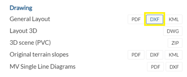
- Export the intended CAD file from RatedPower;
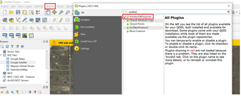
- Open QGIS, click in the "plugin" button on the top bar, and select "Manage and Install Plugins". In the window that will open you'll need to look for and install "AnotherDXFImporter".
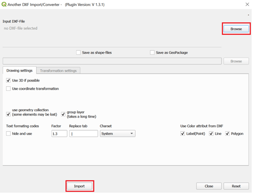
- Once you have it installed, you can click on the vector tab, DXF import/Convert and "Import". You'll choose the exported CAD file from RatedPower.
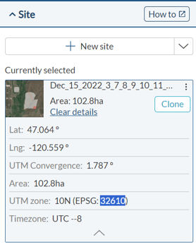
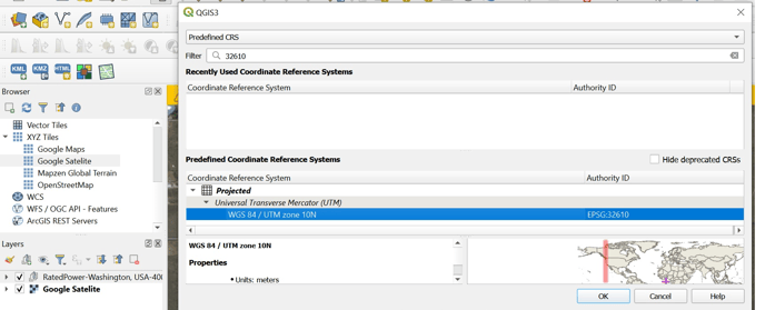
- The next step would be to close the window above, select the new added folder, right click the file and choose "Set Group CRS". This value you can obtain in RatedPower under the site. You can just copy and past it on the QGIS window.
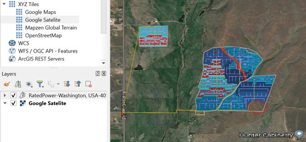
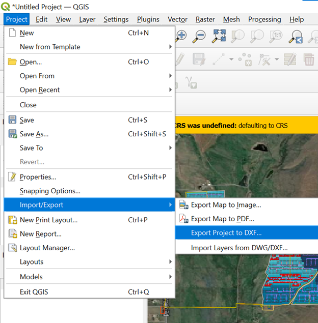
- If you have the satellite layer on, you should be able to see the site at the right spot. From here we'll click on Project -> Import/Export -> Export Project to DXF
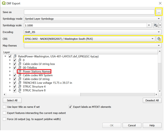
- You'll need to choose the location to save the layout, choose the new CRS, and also "uncheck" the power station names. Having this on checked can cause some issues when opening on CAD.
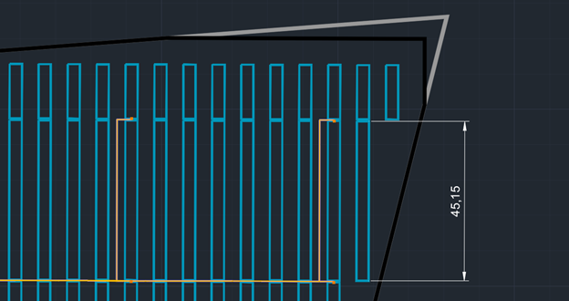
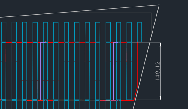
Opening both the original layout and the converted one on CAD, we can see the differences:
Metric System
Imperial System
Unfortunately this conversion is not going to match 100% of the original layout, and some elements might be missing or changed. Those will be:
- Text codes
- Road width
- Slightly rotated due to CRS conversion.
We recommend doing the coordinate transformation in AutoCAD Map 3D or Civil 3D in case you have the license.
For any other questions or more information regarding this topic, you can contact us at: support@ratedpower.com