In order to deliver accurate production estimates, it is crucial to understand what factors reduce the energy yield of your PV plant and by how much. In this article, we explore losses from module's faces (back-front) and electrical system.
Introduction
It's crucial to be able to predict the solar installation's output with accuracy. However, a variety of factors, including the physical properties of the components and design as well as external elements like dust and shade, have an impact on how much energy the PV system will produce.
From the PV modules to the grid, the losses are arranged based on the design order. Therefore, the PV module losses come first, followed by those of the string, inverter, transformer, substation and grid.
Once the design is simulated, the losses can be viewed in the energy tab on the right side of the screen. They are classified into three groups:
- Front-face losses
- Back-face losses (if using bifacial modules)
- Electrical system losses
Front-face losses
As the name implies, these losses occur on the front face of the modules and are directly related to far shadings/horizon, near shadings, soiling and Incidence Angle Modifier (IAM).
- Far shading
The presence of obstacles in the horizon line (such as hills or buildings) will negatively impact the irradiance reaching the photovoltaic modules. This will occur in the times of day when the sun elevation is lower. An obstacle is usually considered to be part of the horizon profile if the size of its shade is more than ten times greater than the size of the photovoltaic plant.
The horizon profile of the photovoltaic plant can be viewed by the energy tab of the design process.
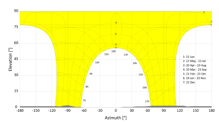
This is an example of horizon profile. A quick way to read this type of graph is to analyze the size of the yellow area, the larger this area is, the more daylight hours there are during a year. Also, you can see the elevation of the sun in different periods of the year (Y axis) versus the azimuth (X axis), where -180º represents the East (sunrise) and 180º the West. The gray areas on the X-axis represent mountains or obstacles on the horizon that cast shadows on the location of the solar plant.
- Near shading
Contiguous rows of photovoltaic modules will block the sunlight to nearby rows whenever the sun elevation is low. These shades will negatively impact the irradiance received by the photovoltaic modules.
This loss is due to the reduced diffuse and albedo irradiance. For trackers, the beam irradiance is unaffected thanks to our backtracking algorithm. - Soiling
The deposition of dirt and dust on the surface of the module causes a direct loss of irradiance known as soiling loss. This impact is greater for oblique sun rays than for perpendicular rays.
The soiling loss is easily minimized by regularly cleaning the photovoltaic modules. Similarly, it is reduced whenever the atmospheric conditions result in the removal of dirt from their surface (through rain or wind). However, in transient conditions of high pollution the loss may be as high as 8 %, e.g. in between cleaning operations. Other conditions which influence the soiling loss are the proximity of roads, the terrain characteristics, or the tilt angle of the modules.
The front-face soiling loss is modeled as an average value constant throughout the whole year. - Incidence Angle Modifier (IAM)
A loss is incurred due to the non-zero angle of incidence of the sun rays on the plane of array, in addition to the cosine effect. A fraction of the light reaching the surface of the modules is reflected by the glass cover protecting them. This loss is computed using an Incidence Angle Modifier (IAM) coefficient, which is a function of the glass used. The front face glass was modeled using the ASHRAE model.
How to reduce front-face losses?
As evidenced in the paragraphs above, the losses appearing on the front face of the module are directly related to the location, weather conditions and geometry of the solar PV plant.
It is in the case of near shadow losses that the plant geometry is considered, since they are related to the shadows between the different structures rows, the diffuse irradiance and the albedo that is reflected on the front face.
To reduce them, the distance between structures (pitch distance) could be increased, but it should be taken into account that by increasing the pitch distance for a given available area, the number of structures that fit is smaller, so it could lead to a drop in the total energy generated.
Back-face losses
The back and front side of the modules share some losses such as near shading and Incidence Angle Modifier (IAM). Some other losses are related only to the back face, such as ground shades effect and ground reflection.
- Ground shades effect
The shades cast on the ground by the structures result in a loss of irradiance for the back-face. Parameters such as the pitch distance between structures, the minimum ground clearance and the transparency fraction affect the value of this loss. - Ground reflection
The ground reflects the irradiance originating from the sky vault. For any given point in the ground determined by its position in relation to the structure axis, the amount of visible sky vault must be quantified.
How to reduce back face losses?
To increase the bifacial gain, it is recommended to increase the minimum ground clearance of the structures (Equipment tab). This way, a higher amount of irradiation will be reflected on the back side contributing to an increase in the specific yield production of the plant. Taller structures require more material and are subject to higher mechanical stresses, which may increase the total cost of the PV plant.
Electrical system losses
Some of the electrical system losses are defined during the design process in the Grid Point, Electrical or Energy tabs, while others depend indirectly on parameters such as the number of modules per string or the DC/AC ratio.
- Module degradation
An initial degradation of the module performance occurs in the first hours of exposure to sunlight, known as the Light Induced Degradation loss (LID).
However, after this initial degradation, a more long-term process takes place which results in a yearly loss of performance.
This degradation occurs due to corrosion of the conductors and a gradual failure of the seal of the back face module. Atmospheric conditions such as high temperature swings, rain, ambient humidity, and salinity may accelerate the corrosion. - Module Temperature
The production of photovoltaic cells is negatively affected by high operation temperatures. The loss is a consequence of the photovoltaic module characteristics. The cell temperature is always higher than the ambient temperature. - Light-Induced Degradation
The light induced degradation occurs in the first hours of exposure the photovoltaic module is exposed to sunlight. After these initial hours, the degradation sets in and is constant for the remaining lifetime of the module. This effect is not usually reflected in the module datasheet. - Bifacial mismatch
The bifacial mismatch is caused by heterogeneous illumination of the back-face. It is more pronounced in 1V single axis trackers where the torque beam casts a shade on the back face and there are photovoltaic cells in the shaded area. This value does not directly translate into the final loss result, as it is applied proportionately to the ratio of front to back irradiance. - Module mismatch
The mismatch loss occurs because of the variation of electrical characteristics between
photovoltaic modules connected in series in an array. This means the modules are not always able to operate at their maximum power operating point.
The presence of partial shadings in an array gives rise to a mismatch between the partially (or completely) shaded modules and the unshaded ones.
This loss can be minimized by increasing the pitch distance between rows, or by using a backtracking system in one-axis trackers.
- Array shading
This value will be different from zero only when fixed structures are used, since for trackers, if silicon-based modules are used, the backtracking algorithm will avoid shadows for any defined pitch distance. If designed with trackers but thin film modules, it is in this case the true tracking algorithm and the module technology itself that prevent these electrical losses from occurring.
For fixed structures, RatedPower recommends a tilt angle based on latitude and a pitch distance that attempts to achieve 4 hours of shadow-free production on the winter solstice day.
These default values produce a reduced value of inter-structure losses, which could be further reduced by increasing the pitch distance or reducing the tilt angle.
- DC Wiring loss
There is a loss due to the ohmic effect incurred in the electrical transmission of DC power. This loss occurs in the cables connecting the photovoltaic module strings to the string boxes and inverters (or directly to the inverters if the plant is designed using a DC bus system).
The value of the transmission losses depends on the cable cross sections and cable lengths, which are usually calculated by specifying a value for the voltage drop in STC conditions.
In RatedPower, this loss is calculated based on the maximum DC voltage drop defined by the user. - Inverter losses
They appear when the inverter operates outside the operation window, and are divided into voltage and power losses, either by not reaching the minimum threshold or by exceeding the maximum value.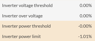
Regarding voltage losses, when a value of modules per string is set below the minimum value of the recommended range in RatedPower, losses will appear since the minimum threshold has not been met. On the other hand, if a very high value of modules per string is defined, losses will occur due to exceeding the maximum voltage of the inverter. These losses are not recommended, as they may cause the inverter to malfunction or even stop working.
The recommended range value of modules per string is based on the voltage of the modules, the maximum input voltage of the inverter and the efficiency of the inverter. For more information on this calculation, we recommend that you read chapter 1 of the Electrical Methodology.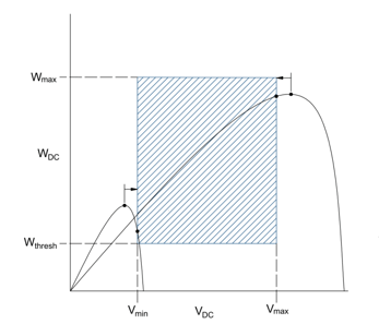
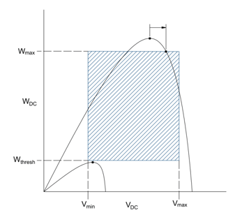
Power losses occur mainly because the maximum DC power limit of the inverter is exceeded, as the inverter's MPPT is forced to change the optimal operating point. Although having a small percentage of these losses is not alarming, the value will start to rise as the value of the DC/AC ratio increases (e.g. a value of 1.5 for a site with high irradiance), as the inverter will not be able to operate at the maximum power point a greater number of times. - Inverter efficiency
The main loss incurred in the electrical inverter is the conversion of DC to AC, usually known as the efficiency loss. Additional losses may occur if the sizing of the DC array with respect to the rated power of the inverter is not optimal (inverter operation window losses). A low power factor may result in over power losses. - AC Wiring loss (inverter to transformer)
The losses incurred in the AC cables due to the ohmic effect depend on the cable cross sections and lengths. The loss is typically specified as a percentage of voltage drop in STC conditions. Because of the short length of the cables connecting inverter to transformer, this loss is usually low. In the case of a central inverter, this loss is 0% as the inverter is inside the power station. - PS transformer loss
The power transformer losses are two-fold: a constant loss value, known as the iron or core loss, and a converted power dependent loss, known as the copper or winding loss. Although these losses are usually very low, because the transformer has a very high efficiency, they must be considered. - MV Wiring loss
The losses incurred in the MV network due to the ohmic effect depend on the cable cross sections and lengths. The loss is typically specified as a percentage of voltage drop in STC conditions. The medium voltage network consists of a series of lines connecting the power station transformers to the substation switch gears.
In RatedPower, this loss is calculated based on the maximum MV voltage drop defined by the user. - Substation transformer loss
The substation power transformer raises the voltage of the power plant AC output to match the grid voltage. The resulting losses for the substation transformer are attributed to the iron and copper components. - Plant unavailability
The unavailability occurs because of scheduled maintenance operations, which may require the plant to be unproductive, and unscheduled stops due to unforeseen circumstances. The loss value is dependent on the plant location.
For more details, please refer to the Energy Yield Methodology.
For any other questions or more information regarding this topic, you can contact us at: support@ratedpower.com