In this article, we will learn how to export a PV Collada (.PVC) tracker scene to PVsyst.
For each design, RatedPower will generate a zip file with one or more .PVC files. This file allows users to export the shading scene from RatedPower to PVsyst. Multiple files are generated only when the size of the PV plant is too big and results in one .PVC file being too heavy to export to PVsyst.
This article will show you how to do this process in the case of trackers:
- Open PVsyst.
- Enter the specified project.
- Go to the 'Near shadings' tab.
- Click on 'Construction / Perspective'.
- On the upper tab, go to File → Import → Import a 3D scene (3DS, DAE, PVC).
- A new window will open, just click on OK. (The units should be set at 'Meters (m)' by default and the 'Automatic' checkbox should be enabled).
![]()
With this, PVsyst will load the 3D scene. Now, given that the scene contains trackers, it is important to enable the backtracking option.
To do so, go to Tools → Backtracking management. Then enable the 'Backtracking' checkbox and click on OK.
![]()
After enabling the backtracking, you are almost done loading the shadings scene. The final step is optional but recommended, it consists in defining the string partition scheme. By default, PVsyst considers that all trackers have one string each. This, however, may not be the case. So, to fix this, you can apply some string partition.
To do so, you can do the following:
- Double-click on any of the trackers/structures.
- On the right-hand sidebar, go the to 'Partition' tab.
- Enable the 'Define partition' checkbox.
- Modify the 'Number of rectangle strings' values to get something similar or close to your actual structure.
- Select the 'All tables of the scene' option.
- Click on the 'Apply' button.
- Click on the 'Close object' button.
![]()
After that, you can click on the 'Close scene' button. This will return you to the 'Near shadings' window where you will have to click on the 'Table' button to generate the shading values.
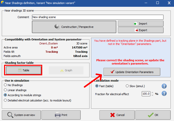
- Before clicking on the 'Table' button, you will need to make sure the electrical configuration and the orientation are properly designed in PVsyst and that they match the design configuration in RatedPower.
- To get the right orientation, you can click on the 'Update orientation parameters' button.
Tips
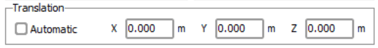
- In some instances (designs with a high capacity), you may need to upload multiple PVCollada files to PVSyst. To do this properly, disable the automatic translation and set the coordinates to 0, 0, 0.
- If you get an error message in PVsyst like below, you can fix it by overwriting the maximum tilt spread for the tracking axis in "Settings" -- "Edit Advanced Parameters" -- "Verifications on General system parameters--Tracking: maximum axis tilt spread".
-3.png?width=541&name=image%20(2)-3.png)
- If you have encountered an error message saying "Several tracking fields defined in this scene. Field "Tracker #X" is incompatible with field "Tracker #Y": the axis tilts difference(X°) is too high.", then you will need to change the value of the limit for ¨Tracking axis tilt spread¨.
To find it, go to ¨¨Settings¨ > ¨Edit advanced parameters¨ > ¨Tracking: Maximum axis tilt spread¨. Following the below screenshot of the menu, please increase the value to avoid the above error message.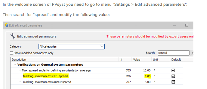
- The setting of bifacial modules and tracker structures will be computed in PVsyst using a 2D model, instead of 3D modeling. For more information regarding PVsyst calculation regarding bifacial systems, please check their article.
For any other questions or more information regarding this topic, you can contact us at: support@ratedpower.com