The discrepancy is generated from the conversion of the KML Google Earth file to CAD.
The site is initially defined in geographic coordinates (latitude and longitude). After that, an autoCAD file in georeferenced UTM coordinates is generated. For this reason, the UTM convergence effect should be taken into account in order to avoid any possible errors when installing the structures. You can find the UTM convergence value expressed in degrees by clicking on the details button of the site inside RatedPower. This value is also reflected in the CAD file in the second tab (print view). This angle is the rotation applied to the CAD version.
This effect can be better understood through the image below:
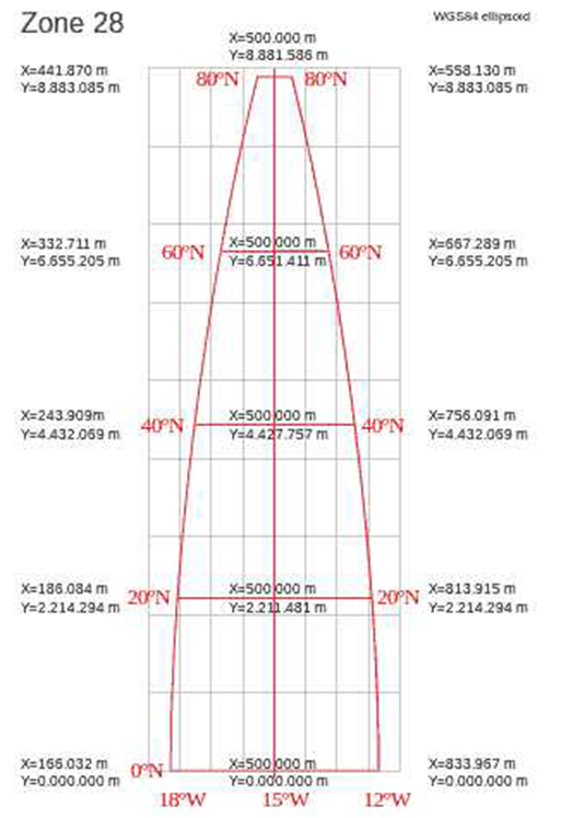
Here, the red lines mark the longitude, and the gray lines represent the UTM coordinates meshes. The convergence is the measurement of the angle between the red line of longitude and the gray one. The convergence effect is more noticeable in the zones separated from the central axis and in the northern part of the grid corresponding to this site. The deviation could reach up to 2 degrees and could have important consequences on the terrain’s occupation/filling and on the energy production of the PV plant.