This article discusses everything related to cables in RatedPower's different generated documents
This article aims to walk you through RatedPower’s cabling-related documents. To make things easier, we will take the medium voltage cables as an example throughout this article. We will start with the list of cables and then branch out to the rest of the related documents.
Before delving in, let us first refresh our memory with the hypotheses used for the design of medium voltage (MV) cables.
MV cables are 3-phase single-core cables, made of aluminum, and insulated by XLPE for the IEC, AUS, and Chinese standards and by XHHN for the NEC. These cables are directly buried in trenches.
MV cables in the list of cables
The listing of cables is an excel sheet that shows the electrical characteristics of all the cables of your PV plant.
Each sheet in the excel file represents a different subsystem of your PV plant. For instance, for a string box configuration, the excel file would have 3 different sheets, one for the string cables, one for the cables from the string boxes to the inverters, and one sheet for the medium voltage cables.
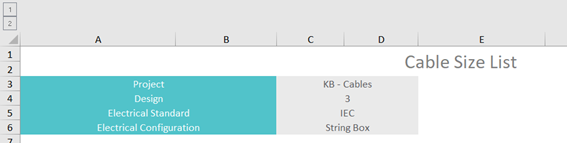
The first thing you will see in the listing of cables, is the project’s name, the design’s number, the chosen electrical standard, and the electrical configuration.
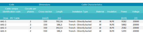
After that, the general information of each cable, from the unique identification code, the cross-section, the number of circuits per phase, the cable’s length, all the way to the type of installation, material, insulation, power, and voltage are presented.
In the following columns, the shown information refers to the different cable sizing criteria. Once the cross-section of a cable is chosen, its voltage drop, its temperature and the short-circuit current that it can withstand are recalculated.
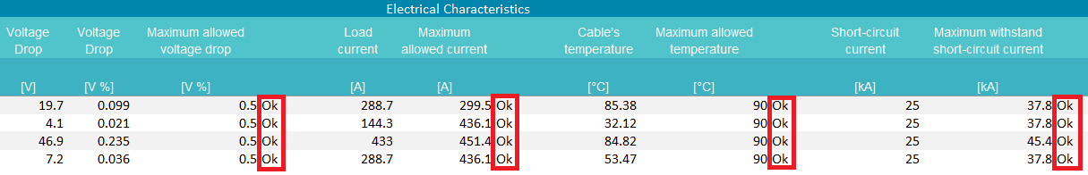
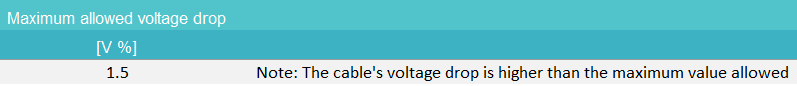
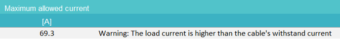
As it can be seen, if a cable complies with all the criteria, an “Ok” is provided right next to it. If, however, any criterion is not complied with, a warning message with the respective severity is shown instead.
This could happen if the available sections selected by the user in the electrical tab are too restrictive, as shown in the following example:
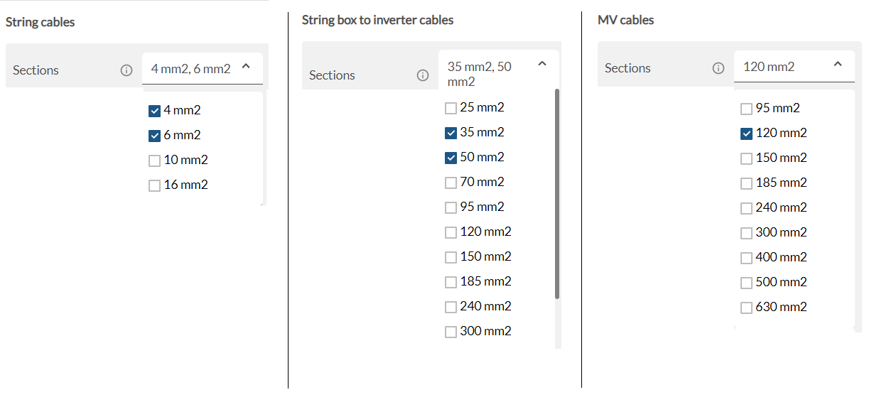
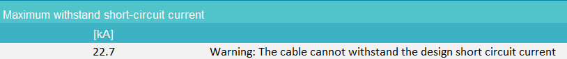
In this case the criteria cannot be met using these sections, so the software will provide the "best" option and display a warning:
For more information, you can refer to Chapter 2 and Annex B of our Electrical Methodology.
Right next to this information, the results of each of the cable sizing criteria are demonstrated. These are the voltage-drop criterion, the short-circuit temperature rise criterion, and the maximum ampacity criterion.
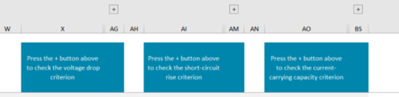
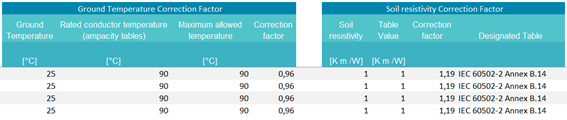
All you need to do is click on the “+” button and these results will be shown. With respect to the maximum ampacity criterion, all the applied correction factors per type of material, insulation, and installation are presented based on the chosen electrical standard. This way, the user can check first-hand all the chosen factors directly from their corresponding tables in the chosen electrical standard.
For more information, refer to Chapter 2 and Annex A of our Electrical Methodology.
Going back to our example of the medium voltage cables, we will focus on the unique identification code, the cross-section, the number of repetitions per phase, and the length of each cable.
There are four medium voltage cables in our PV plant:
- Cable AA1-1, 150 mm2, 2 repetitions per phase, and 702 m of length.
- Cable AA1-2, 150 mm2, 2 repetitions per phase, and 186 m of length.
- Cable AA1-3, 150 mm2, 2 repetitions per phase, and 392 m of length.
- Cable AA1-4, 150 mm2, 2 repetitions per phase, and 186 m of length.
The unique identification code AA1-1 refers to the available area in which this cable is located (AA1) while the number of the cable (1) corresponds to the power station.
A similar pattern when it comes to the cables’ nomenclature is followed for the rest of the subsystems. For instance, a string cable whose identification code is AA1-1-0-0-0 would be a cable located in the first available area (AA1), in the first power station (1), in the first inverter inside this power station (0), in the first string box connected to the first inverter (0) and it would be the first string cable (0).
MV cables in the layout
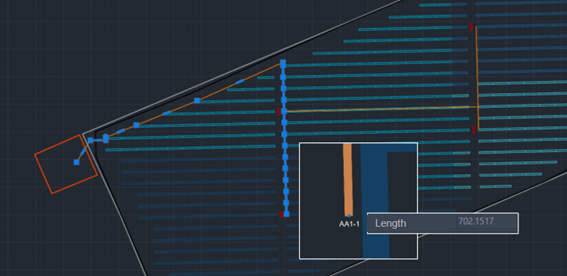
To check where our MV cable denoted by AA1-1 is located, all we need to do is open the General Layout in AutoCAD and search for this identification code. We can observe that the length of the cable measured in AutoCAD is the same as the one shown in the list of cables.
MV cables in the MV single-line diagram
We can also find our MV cable in the MV single-line diagram. The AA1-1 cable goes from power station number 1 towards the substation.
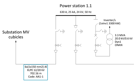
The MV single line diagram shows the cable’s material, insulation, its code, and the length measured in AutoCAD. Additional information like the cross-section and the number of repetitions per phase are also represented, albeit a bit different from how it is shown in the listing of cables.
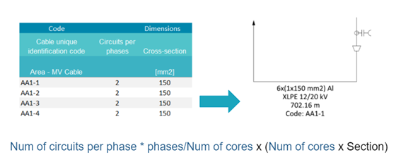
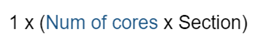
Cable AA1 is a single core (Num of cores = 1), 3-phase cable (phases = 3) and requires 2 cross-sections per phase (Num of circuits per phase = 2). Thus, in the single line diagram, we can observe the following nomenclature: 2*3/1x(1x150) = 6x(1x150 mm2).
MV cables in the BOQ
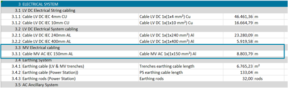
But how can we properly price these MV cables? This information can be found in the BOQ. The first thing that we can notice here is the difference in cable nomenclature between the BOQ and the single-line diagram. The BOQ follows the next pattern.
This makes pricing cables much easier. In our case, since the cable is a single-core cable, the result would be 1x(1x150 mm2).
This way, when pricing the single-core cable, its length is calculated in the following way.
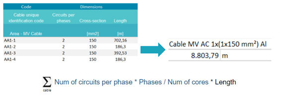
In our case, the total length is (2*3/1*702) + (2*3/1*186) + (2*3/1*392) + (2*3/1*186) = 8803 m
Remark: Cables in the LV single-line diagram
The cables that are represented in the low voltage single line diagram by electrical level (string cables, box cables, mv cables, etc..) show the sections that can be found in the bill of quantities.
So, for the following simulation with a string inverter electrical configuration and its bill of quantities...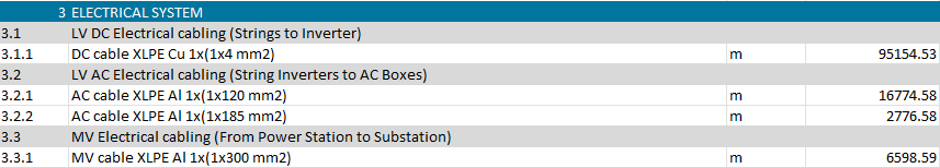
...4mm2 sections can be found in the single line diagram that represents the connection between the modules and the string inverter….
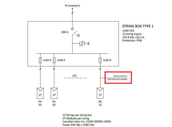
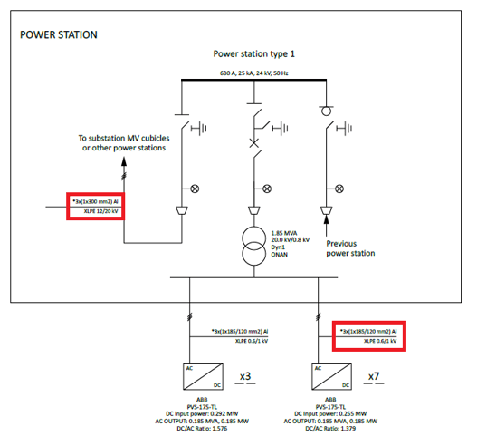
...and 120/185 mm2 sections for cables that connect the string inverter to the power station and 300 mm2 for medium voltage cables
Summary
To conclude, the cables are sized regarding three criteria: the voltage-drop criterion, the short-circuit temperature rise criterion, and the maximum ampacity criterion. The cables can be seen in several documents: the listing of cables, the general layout in .dxf format, the Bill of Quantities and the Single Line Diagrams (LV, MV, LV-MV). Moreover, each cable is identified by a unique code.
For any other questions or more information regarding this topic, you can contact us at: support@ratedpower.com