This article explains how to set installation limits, discard structures, and perform earthworks
In RatedPower, inside the design process, you will find a tab called "Topography". Here, users can set their installation limits: maximum slope limit in the North-South direction, maximum slope limit in the East-West direction, maximum linked-row slope limit, and terrain undulation.
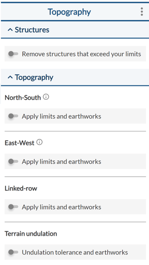
All criteria (except for the linked-row criterion) have two options, an installation or tolerance limit, and an earthworks (cut & fill) mode.
Linked row criterion
Let’s start with the linked-row structure first. This limit is only available when a linked-row tracker is selected.
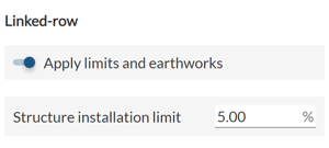
After enabling this option, you can set the maximum slope limit. Let’s assume that the set slope limit is 5% as shown in the image above. RatedPower will remove any linked-row tracker that has a slope of 5% or above between its rows. Even if a linked-row tracker consists of 12 rows and the slope between only 2 of these rows is above the set limit, the whole linked-row tracker will be discarded from the final design.
North-South criteria
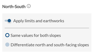
To apply the North-South criterion, the first step is to activate the "Apply limits and earthworks" button.
Then you will be able to choose between two options:
- Apply the same value for both slopes
- Differentiate between north and south slopes
1. For fixed structures, RatedPower considers the North-South direction as perpendicular to the structure’s axis, while for trackers or East-West structures, it is considered parallel to the structure’s axis. The direction rotates with the layout if a rotation is applied. In cases where the angle of rotation is greater than 90º, North and South will be swapped to align with the actual North-South orientation.
2. Sometimes the north/south-facing slopes are also referred to as "Negative/Positive slopes" to suggest their negative or positive impact on energy yield.
Option 1: Same values for both slopes
If you choose this option, the software will check the slope value below the structure (whether it's a tracker or a fixed structure) in the north-south direction. For example, using the example shown in the image below, any structure installed above a north-south slope of 7 % or more will be removed from the final design.
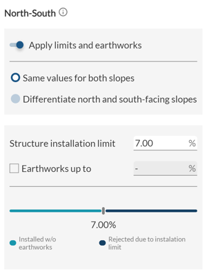 What happens if we also activate the "Earthworks up to" option, as shown in the image below?
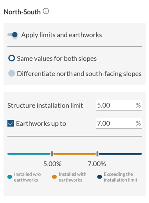
In this specific case, RatedPower will apply earthworks to the terrain found under a structure as long as its North-South slope is between 5 and 7%. In other words, it will apply all the necessary cut and fill to reduce this slope to 5%. However, if the North-South slope is initially greater than 7%, the structure will be removed from the final design.
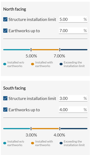
Option 2: Differentiate between north and south slopes
This option allows you to set an installation limit and choose whether or not to apply earthworks for North Slopes and South slopes. You can either choose to set limits for both slopes or only one by clicking on the checkboxes. The logic used by the software for the removal of structures and the application of earthworks is the same as in the case of option 1.
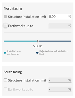
 If you choose to differentiate slopes and set limits in only one slope, the checkbox will be disabled as it is mandatory to have at least one limit.
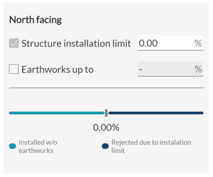
 If you want to remove all the structures with a South(or North) facing slope, you should put a slope limit of 0%.
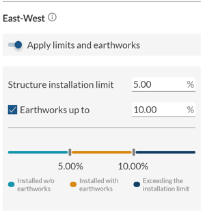
East - West criterion
To apply the East-West criterion, the first step is to click on the "Apply Limits and Earthworks" button. For this criterion, you can only apply the same limit for both East and West-facing slopes (similar to option 1 for North-South slopes).
For fixed structures, RatedPower considers the East-West direction to be parallel to the structure's axis. For trackers or East-West structures, the East-West direction is considered to be perpendicular to the structure's axis. It will rotate along with the layout if a rotation is applied.
Terrain undulation criterion
The final criterion is the terrain undulation criterion. This parameter allows users to set a maximum limit of pile length difference between the shortest and the longest pile of the same structure.
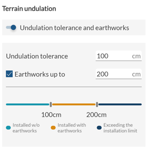
In the example shown in the image above, RatedPower will apply all the necessary earthworks for structures that have a difference of 100 to 200 cm in length between their shortest and longest piles. The goal is to decrease this difference down to 100 cm. If this difference is initially above 200 cm, the structure will be removed from the final design.
Based on these results, RatedPower will calculate the total necessary cut and fill volume and include these values in the Design Report and the BOQ. It will also generate Listing of Posts and Terrain XYZ spreadsheets, a Topography Analysis DXF, and a Structure Profiles zip file that includes various CAD files.
Summary
RatedPower's topography limitations and earthwork constraints tool allows users to set their topography criteria for the final design and generates a set of relevant documentation.
For any other questions or more information regarding this topic, you can contact us at: support@ratedpower.com