We'll teach you the best practices to fully customize each overhead line in your PV plant.
In this article, you will learn how to customize overhead lines (OHL), understanding how each parameter will influence the final design.
To customize an OHL you need first to define its path in "Site Creation". Give a look to this article to learn how.
To customize an OHL go to "Grid Point" and select the OHL of interest.

Here follows a detailed description of each parameter you can set for each OHL in your plant.
Main Parameters
1. Capacity overestimation
RatedPower estimates the capacity automatically based on the plant design. You can increase this value to adapt to your needs, and the designing of the OHL will be based on this over-estimated capacity.

2. Number of circuits
You will be able to change the number of circuits to be used for your OHL, either 1 (Simplex) or 2 (Duplex).

3. Number of conductors per phase
You can decide how many conductors to include per phase, you can choose from 1 up to 4.

4. Right way of buffer
Here you can set the width of the Right of Way Buffer. This will be used to create a restricted area in case your OHL is crossing the available area (AA).

RatedPower will try to avoid placing spotting towers in the available area as much as possible. A warning message will appear in the OHL drawing and in the interface if that is not possible.

5. Pollution level
You will also have the possibility to select the level of pollution, choosing between light, medium, heavy and very heavy (based on the IEC standard).

Based on the pollution level and the IEC standard, the recommended minimum nominal creepage distance is displayed and applied.
6. Target span
You can define the target span, i.e. the distance between tower. This parameter is used to calculate the maximum span, that can be up to 15% larger than the target span.

7. Phase conductor
You can choose to either use AAAC (Aluminum composed conductors) or ACSR (Aluminum and steel composition). We provide you with a range of conductors for each one which is used widely in the industry. 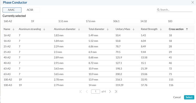
8. Earth wire
RatedPower provides you with various fiber optics earth wires to choose from.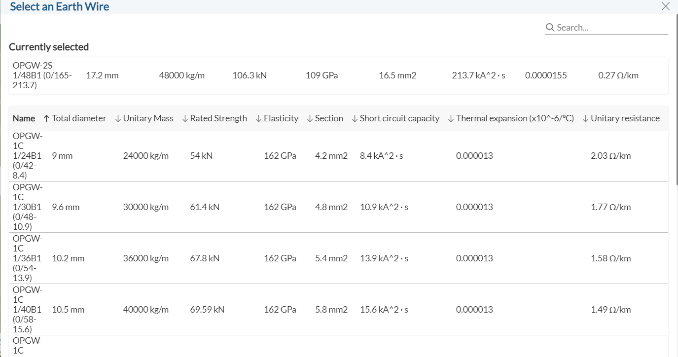
9. Tower shape
You will have 6 options for your tower shapes depending on how many circuits you have.
- If you have a single circuit, the following tower shapes are available.

- If you have a double-circuit transmission line, the following tower shapes are available.

Design Criteria
The calculation and design will be based on the inputs you set, more information on the considerations of each input can be found in the Overhead Line Methodology.
You can define exclusion zones over your OHL. RatedPower will take these into consideration when placing the different towers. Whenever viable, no towers shall be placed in these restricted areas.
The only exception is angle towers, i.e. where the OHL path is changing direction.
When that is not possible, the spotting towers will be placed in the RAs, however, a warning message will be shown in the OHL drawing and in the interface as can be seen below.
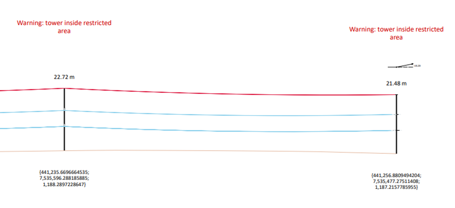

The user can view the final OHL path on the overview map, which includes information about each tower and possible warnings.
-3.png?width=688&height=513&name=image%20(3)-3.png)
For any other questions or more information regarding this topic, you can contact us at: support@ratedpower.com