This article focuses on how you can set a power factor in RatedPower and on the general understanding of this concept.
Introduction
A utility-scale PV plant, as any other grid-connected generation facility, has to fulfill a series of grid-mandated requirements. Reactive power regulation is one example.
This can be embodied by a certain inductive power factor value that your PV plant must be able to reach at any given point.
There are three main terms to understand to talk about power factor: apparent power, active power, and reactive power. The apparent power is the total power. It is measured in volt amperes (VA), same unit as the power of your inverter is expressed in (kVA). The apparent power encompasses the two other: active and reactive power. When talking about a PV plant’s output, the term that we tend to refer to is the active power, measured in watts (W). The active power is the useful part of the apparent power, what will be counted as energy output over time. The reactive power is the portion of the apparent power that will not translate into electricity generation. It is measured in reactive VAr; the "r" stands for reactive. The power factor, to a certain extent, defines how much active power and how much reactive power there is in the apparent power.
You may be more familiar with the term cosine of phi, it is a synonym for power factor. The angle phi fixes the relation between active power (P) and reactive power (Q). 
The cosine of phi represents how much active power there is given an apparent power (S).
The closer to 1 (the smaller the angle), the more active power we end up with.
At RatedPower, we are aware that reactive power compensation is mandatory. In order to reflect this reality of the energy industry, we have developed a tool that allows you to define a power factor for your PV plant and BESS in RatedPower. You can study early on in the development of your project how this effect will influence your final design.
Overview
The power factor tool is the Grid Point tab, under the section 'Grid Requirements'.
Enable this functionality by clicking on the checkbox as shown in Figure 1. By doing this, you will be sizing your AC capacity accounting for reactive power. There are 2 available strategies for power factor sizing and thus reactive power compensation:
-
- Installing additional inverters to cover the entire DC field.
- Adding both inverters in the field and capacitor banks in the substation.
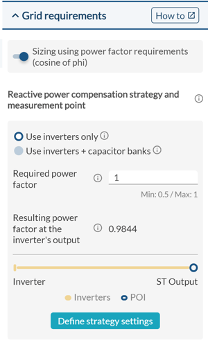
Figure 1 - Power factor in RatedPower
Depending on the chosen strategy, you can define where your power factor should be measured and the value to measure there ('required power factor'). As shown in Figure 2, for inverters only strategy you can define this point either at the substation's input or at its output.
Figure 2 - Power Factor measurement spot (a. Only Inverters strategy)
Should you have adopted an inverters and capacitor banks strategy, you can define the power factor correction point at the substation's input, at the substation's output, or at the end of the Overhead Line (OHL), at the Point of Interconnection (Figure 3).
Figure 3 - Power Factor measurement spot (b. Inverters + Capacitor Banks strategy)
You can check more information regarding Capacitor Banks strategy in our article: How to define Capacitor Banks in RatedPower
Once you define your required power factor value at the selected point, RatedPower will showcase the resulting power factor at the inverter's output automatically. Further on, when you generate your design, the software will calculate the reactive power that your plant will yield. This value is provided in the Energy Report.
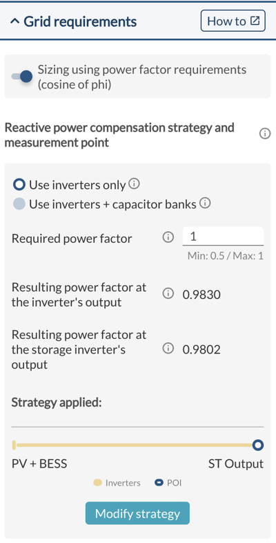
BESS Power Factor Requirements
The AC-coupled battery system can also be sized by considering the power factor requirements. To comply with the requirements defined by the user, the system calculates the required power factor at the storage inverter's output, just like for the PV plant. You will then find an additional line displaying the resulting power factor at the storage inverter's output.
To account for the power factor of BESS, AC-coupled battery storage must be enabled. Please take a look at our article on AC-coupled battery storage for more information.
How is the resulting power factor at the inverter's output calculated?
To have a better understanding of this matter, we first need to set all the parameters that RatedPower offers and which affect the power factor at the inverter output.
In RatedPower, you can enable the transformer losses for the substation, power stations, and storage PCS. And since the software allows you to simulate the basic design of a substation, you can opt between a switching and breaking station or a substation (as shown below in Figure 4).
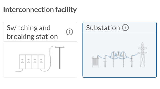 Figure 4 - Interconnection facilities in RatedPower
Does changing the Transformer Losses affect my Power Factor?
We will now explain how varying these aforementioned parameters affects the resulting power factor inside RatedPower while scratching the surface of why such changes occur.
RatedPower allows you to modify the transformer’s iron and copper losses. Modifying these losses (either in the substation, power stations, or PCS) will affect both the active and reactive power losses in the designated transformer. This will affect the resulting power factor as long as the power factor’s measurement point is placed after the transformer. In other words, choosing the power factor at the substation input will cause changes in the power station transformer losses to affect the resulting power factor at the inverter's output. Similarly, changes in the PCS transformer losses will impact the resulting power factor at the storage inverter's output. On the other hand, if the power factor is selected at the substation output, any variation in the power station or substation transformer losses will affect the resulting inverter power factor, and the same goes for the PCS.
These two parameters (transformer losses and the resulting inverter power factor) are actually directly proportional, so increasing one will increase the other. This direct proportionality is due to the relation between transformer active and reactive power losses. The higher these active power losses are, the lower the reactive power that needs to be compensated, and thus the resulting power factor at the inverter output will be higher.
What does placing a value of Zero in the Transformer Losses imply?
Just as mentioned above, modifying the transformer’s iron and copper losses will affect both the active and the reactive power. Placing a value of zero for these two losses in RatedPower will mean that the active power loss will be canceled out, but the reactive power loss will still be taken into account as it depends on various other factors. This will cause the reactive power loss to increase and thus the resulting inverter power factor to decrease.
Is there a way to disable both the Transformer's Active and Reactive Power Losses?
To disable both the transformer's active and reactive power losses at the same time, simply disable the respective option in RatedPower. This, obviously, will not reflect the actual functioning of a transformer, as now, the transformer will be an ideal one with no losses incurred. In reality, there are always going to be both active and reactive power losses in every transformer, and for this reason, we highly recommend that you keep this option enabled. Disabling these losses completely will result in a higher inverter output power factor.
It will also increase the PV plant’s PR and its specific production. This is due to some losses being lower when this option is disabled, mainly the inverter power factor loss, and on a smaller scale, different wiring losses.
Why does the Energy Report sometimes show a Different Power Factor from the one I selected?
An interesting aspect to highlight is that the final calculated power factor that appears in the Energy Report could be different from the one that you specify. In order to understand why this occurs, it is necessary to know how this whole calculation flow takes place.
While selecting the equipment and determining the different parameters of your project within RatedPower, the software won’t know how much total capacity your PV plant has until you reach the “Layout” tab. In order to calculate the inverter’s resulting power factor, however, RatedPower needs to know this total capacity. So to get this information, it estimates the total capacity of your PV plant based on its size and electrical configuration.
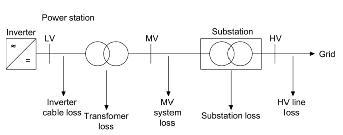
It then starts applying the different losses in the transformers (active and reactive power losses) and the wiring/cables (active power losses) until it reaches the inverter output. So it starts from the selected power factor measurement point and goes back towards the inverters. This result is now used to calculate the power factor at three different points: the substation’s input, its output, and the grid connection point. This calculation is done in the forward direction using the previous result and then applying it to the actual total capacity of your PV plant which at this point (simulation window) is accurately calculated. This could cause some discrepancies between the predetermined power factor value and the one that appears in the Energy Report. In the following picture, you can see all the applicable losses for the power factor calculation:
Let's see an example...
As mentioned above, following the inverters-only strategy and enabling the power factor in RatedPower will cause more inverters to be installed to compensate for the reactive power. This can be seen better through the example of Figure 5 where, to maintain the same total capacity in your PV plant at a lower power factor, more inverters need to be installed.
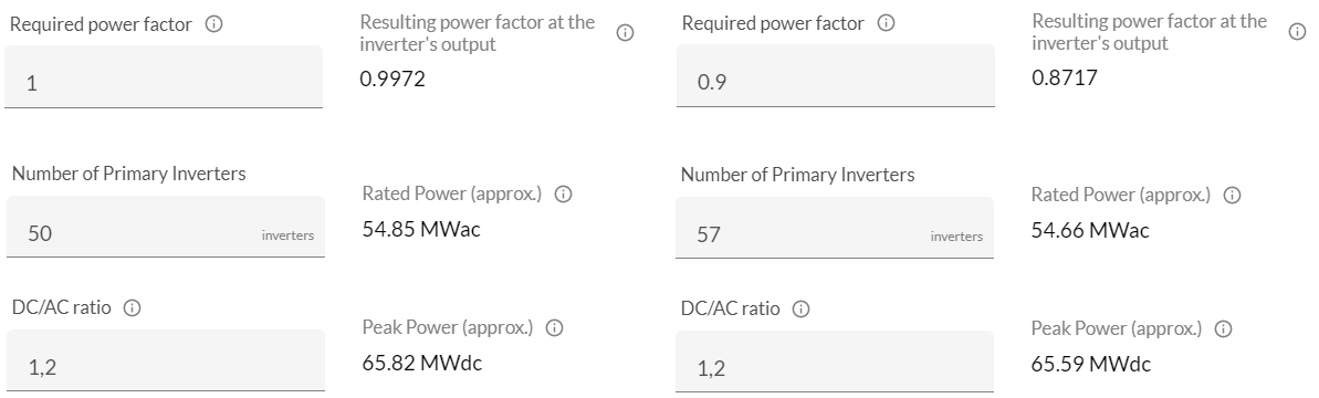
Figure 5 - PV plant with two different Power Factors (a. Only inverters strategy)
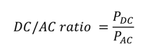
This can be understood better by observing Equation 1.
Equation 1:
Where:
- PDC is the peak DC power output of the PV plant.
- PAC is the nominal AC power output of the PV plant. PAC = SAC * Power factor (where SAC is the total apparent AC power output of the plant).
Thus, when the power factor is less than 1, PAC becomes smaller thus increasing the DC/AC ratio. Our goal is to always maintain the peak power and the DC/AC ratio fixed. This is why the denominator of the previous equation should be increased. Since the power factor is also fixed, we are only left with the option of increasing the AC power which can be done by increasing the number of inverters.
This is how enabling a power factor works in RatedPower. We hope that you have enjoyed the ride and got a clear understanding of the different aspects to be considered regarding this topic. Take care!
For more information regarding this topic you can contact the Support team at support@ratedpower.com