Do you want to add battery storage to your PV plant? Design your hybrid PV + AC-coupled BESS plant in RatedPower.
Introduction
Now, in RatedPower, you can design an AC-coupled battery energy storage system (BESS). By defining an available area for the storage system in your site, as well as the electrical parameters of the system, you will get the basic engineering of your system and a BESS design report.
How to add batteries to your site
There are two ways that you can add batteries. One would be to do it on Google Earth and upload the file to RatedPower. And the other would be to create it using the site creator inside the software.
Definition of the storage area in the KML
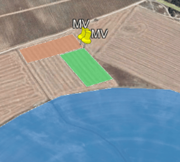
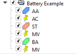
First, it is essential to define a battery polygon (BA) and an MV placemark within that polygon.
The size of the user-defined area will determine the space available to install the storage system. The MV point will be the interconnection point between the battery area and the substation.
Some requirements must be considered so that RatedPower can recognize that area as the battery area:
- The polygon defining the area of the batteries must be called BA.
- The MV placemark is mandatory and is placed inside the BA.
- The battery polygon cannot be placed inside any AA polygon.
- The battery polygon has to be located outside the ST polygon.
- A restricted area (RA) cannot be placed inside the BA.
Definition of the storage area inside RatedPower
After getting into the site creator interface (as per the article on how to create a site directly inside RatedPower), you will be able to select the "Polygon" box to draw the BESS area, and then "Placemark" to place the MV point.
How to define the minimum BESS unit?
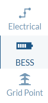
Once the KML is imported into RatedPower, with the BA defined for the storage system, the "BESS" tab is enabled in the design process. This is where we will design the system.
First, within this tab, the electrical parameters of the unit are defined. The minimum unit or block of the BESS is the set of a PCS and the containers connected to it.
- Power Conversion System (PCS): In this first section within the BESS tab, the inverter type and the number of inverters per PCS are selected, thus establishing the power of the PCS or minimum unit of the system.
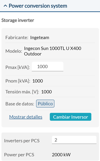
In this example, the chosen inverter has a power of 1000 kVA, and the number of inverters per PCS is 2, so the power of the PCS is 2000 kW.
- Battery container: in RatedPower, we assume that the storage solution is modular. As a user, you will set the capacity of a battery container. Alternatively, you can set the capacity of a single battery rack and the number of racks to include per container.
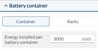
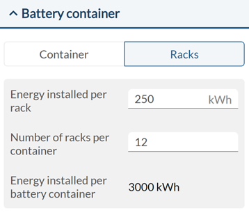
RatedPower will install the necessary number of containers according to the system requirements.
How to achieve your power and capacity requirements?
After having defined the power of the PCS and the capacity of a container, you'll need to define the BESS requirements. This section establishes both the power requirements and the supply hours of the BESS.
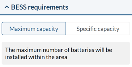
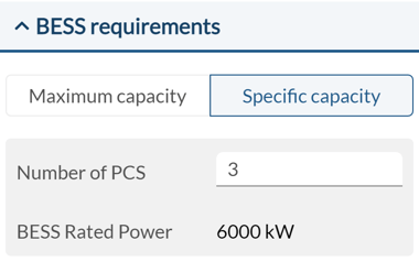
First, choose between maximum capacity or specific capacity.
- Maximum capacity: selecting this option, the maximum possible power will be installed in the area defined for the BESS.
- Specific capacity: In this section, you can configure a specific size for the battery system by defining the number of PCS you want to install. The system power will be the multiple of the PCS power.
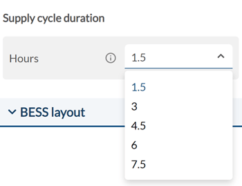
You can now define the supply time. The supply cycle duration is calculated as capacity (MWh) divided by rated power (MW). For example, a 2000 kW PCS and a 3000 kWh container, the supply time (time taken for a complete charge or discharge cycle) will be 1.5 hours. If you connect two battery containers (6000 kWh) to the same PCS, you would have a system with 3 hours of supply.
BESS Power Factor Requirements
The AC-coupled battery system can be sized by taking into account the power factor requirements. To comply with the requirements defined by the user, the system calculates the required power factor at the storage inverter's output, which allows the battery system to compensate for reactive power.
To enable the power factor requirements, navigate to the Grid Point tab and select the Grid Requirements option. When setting the required power factor at the chosen measurement point, RatedPower calculates the resulting power factor at the storage inverter's output.
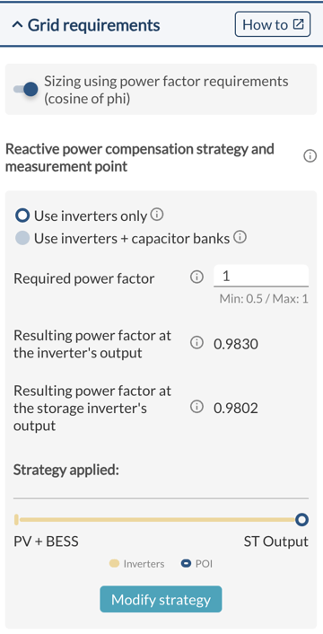
The storage power factor requirements are only displayed when AC-coupled BESS is enabled.
Moreover, the resulting power factor at the storage inverter's output is also displayed when modifying the strategies for compensating reactive power:
- Using inverters only
- Using inverters and capacitor banks
For more information on how these strategies work, please refer to the power factor article.
Additionally, users can enable or disable transformer losses of the power conversion system under the BESS tab:
-3.png?width=336&height=720&name=image%20(5)-3.png)
When the sizing using power factor requirements is turned on, the rated power of the power conversion system can be calculated using the following equation:
PPCS = SPCS x PF
where:
- SPCS is the capacity of the power conversion system, which is the sum of the apparent power of the storage inverters in VA.
- PF is the resulting power factor at the output of the storage inverter.
The results will now display the active power. For example, for the PCS in the image above:
BESS Layout
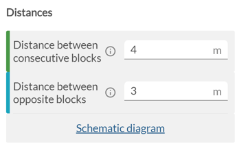
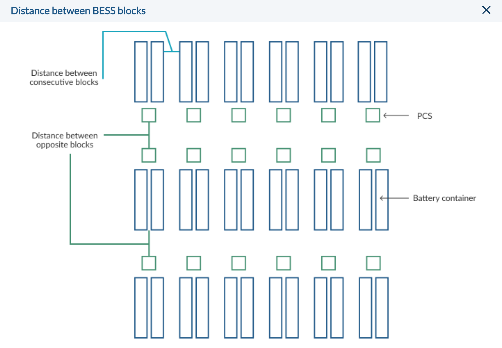
In the BESS layout section, you can define the dimensions of both PCS and containers, distances between blocks, and the BESS rotation angle.
-png.png?width=284&name=image%20(4)-png.png)
The distance between adjacent blocks and the distance between opposing blocks can be also defined by the user. According to the NFPA 855 standard, the safety distances between containers or between containers and PCS are fixed: 0.9144 m (3 ft) and 1.524 m (5 ft), respectively.
In addition, the user can edit the BESS placement by customizing the orientation angle. The orientation angle plays a role in determining the system's efficiency and space utilization.
Users are provided with three distinct options to set the BESS orientation according to their specific requirements.
-png.png)
- Vertical alignment (90º): This option allows the user to choose a vertical BESS orientation, enabling efficient use of vertical space.
- Horizontal alignment (0º): By selecting this option, the BESS layout will be aligned horizontally, ensuring maximum efficiency in terms of horizontal space utilization.
- Rotated (recommended/user input): For a more personalized approach, users have the flexibility to define a custom orientation angle that aligns with their specific project needs or site characteristics.
- Initially, RatedPower provides a recommended rotation angle shown in the "Rotated" option to optimize the BESS layout and maximize the occupancy of the BA area.
- The angles indicate a clockwise rotation. In addition, each PCS will be oriented towards the direction of the BESS MV point.
Results
RatedPower provides the following outputs and documents for the design of the BESS.
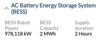
The top bar of the results screen will provide the installed capacity, the rated power, and the supply duration of the complete system.

The BESS layout and a system design report are generated as documentation. The rest of the PV plant documents (SLDs, reports) will include references to the BESS system.
BESS 1.0
This is the first tool that has been developed for the design of storage systems in RatedPower. We want to keep adding functionalities in this direction, starting with offering DC-coupled BESS design tools. If this is of interest to you and you feel like collaborating, your suggestions are more than welcome.
Energy Yield Results
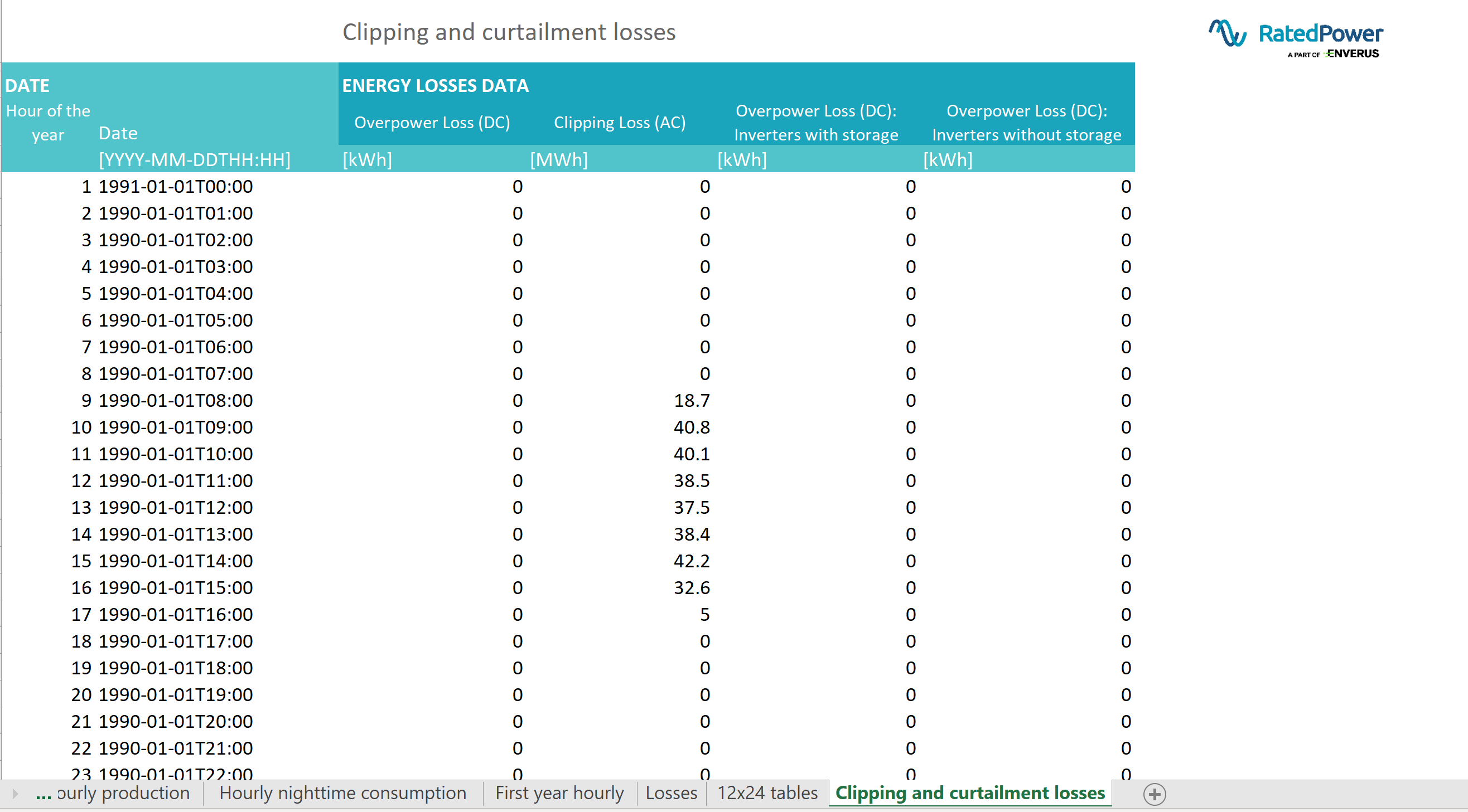
The "Clipping and curtailment losses" tab was added to all the Energy Yield Results excel sheets when the BESS option was launched. Even if no BESS is added to the design, we'll find:
- Overpower Loss (DC): This loss corresponds to the energy that is theoretically available to charge a DC-coupled battery and its equal to the sum of the two following losses:
- Overpower Loss (DC) - Inverters with storage: these inverters are in a PS (power station) where a DC/DC converter.
- Overpower Loss (DC) - Inverters without storage: these inverters are in a PS (power station) where no DC/DC converter is installed. Therefore this overpower cannot be stored by a DC-coupled BESS.
- Clipping Loss (AC): If the user has set a curtailment at Delivery Point (active power limit input, found under Layout<Energy Requirements), the PV plant may experience energy clipping at the interconnection facility. This loss corresponds to the energy that is theoretically available to charge a AC-coupled battery.
For now, RatedPower does not calculate any energy storage flows. We have focused on providing the basic engineering of the BESS (description, layout interconnection) and the energy that would be available to charge the BESS. This is, the excess energy that the PV plant is experiencing because of clipping losses at the inverter or curtailment losses at POI.
Charge or discharge dispatch strategies of these systems are out of scope at the moment. The only information we provide is the columns mentioned above, which are the excess energy that is lost if no battery energy storage system uses it.
For further information or if you would like to give us feedback, please contact us at support@ratedpower.com