Learn what thin-film (CdTe) modules are, which considerations to take into account, and how their energy yield is calculated.
Introduction
As you may know, CdTe modules are an alternative to the traditional, crystalline silicon option. There are differences between both technologies, the most remarkable of them being that the energy model that is used to calculate the production of silicon-based cells is not fully applicable to cadmium tellurium cells.
At RatedPower, we have developed a parallel energy model to accurately simulate CdTe technology PV plants.
FirstSolar, the #1 thin-film module manufacturer, has collaborated with RatedPower by providing their complete up-to-date catalogue. At your fingertips, you can find over 50 ready-to-use FirstSolar products in our public database.
Users can also feel free to upload thin-film modules from other brands to their private database.
Thin-film modules are built from a different material (CdTe) than the traditional alternative; moreover, the cells within the PV module are distributed differently. This requires some adjustments to the way a PV plant is designed.
Considerations for the energy calculation model
Let's say you decide to select a CdTe module during the Design Process.
The energy calculation algorithm will go through certain adjustments in order to account for the specific behaviour of these modules:
Electrical shading and true tracking
The solar cells in thin-film modules are distributed longitudinally. This means that shading impacts all of them equally. Therefore, electrical shading (array shading) doesn’t apply, and true tracking (perpendicular to the sun's position) is preferable to backtracking as it will increase energy production.
Spectral correction
The power class and behaviour of all PV modules is calculated under STC conditions. These conditions consider not only a certain cell temperature, irradiance, etc. but also a standard distribution of the spectrum.
In the case of CdTe modules, the mismatch between the real distribution of the spectrum and the standard distribution of the spectrum has an impact on production. CdTe modules perform better in wet locations (computed as a gain) and worse in arid locations (computed as a loss).
How does RatedPower know the conditions of the location?
Via the meteorological data selected. If it includes information about the Precipitable Water or the Relative Humidity (information readily available in the PVGIS 5 default source), a spectral correction will be applied.
Recombination losses
Due to the material that is used for the manufacturing of these modules, a chemical recombination process occurs in CdTe cells. The consequence of this phenomenon is represented as a recombination loss, applied to the photocurrent in the standard one diode model. The magnitude of the loss depends on a parameter that we extract from the PAN file of your module.
Check out our Energy Methodology if you want to become an expert in how the energy production is calculated. It has been updated to include all thin film insights!
Considerations for the electrical design
CdTe modules have a higher voltage than silicon-based modules (around 5 to 6 times higher).
To connect one string of CdTe modules in series that reaches the same voltage as the average silicon module string, we need around 5 to 6 times fewer modules. An average silicon string size is around 30 modules per string, whereas a thin film string is formed with just 5 or 6 modules.
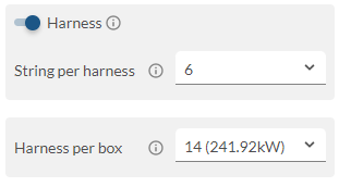
Let’s say we now want to connect our CdTe strings in parallel to a LV collector (String Box, DC Bus or String Inverter). Following a similar logic, the number of inputs per LV collector is going to be around 5 to 6 times higher than usual. Most LV collectors will not accept such a big number of inputs. We need a way to decrease the number of inputs. How? With harnesses.
With CdTe modules, a very common intermediate step between the DC field and the LV collector is to use DC harness cables, which collect a certain number of strings into one before reaching the LV collector.
DC harness cables can be used with all types and technologies of PV modules
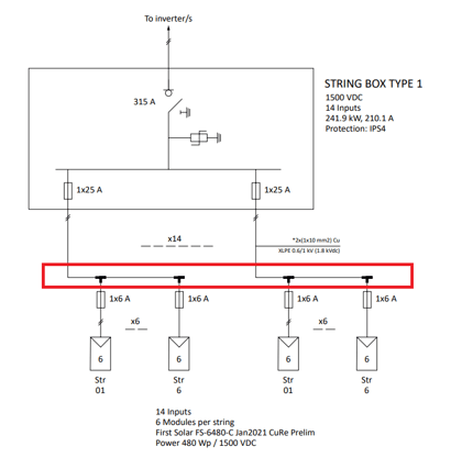
A DC harness cable in real life looks like the following image:
-4.png?width=342&name=image%20(1)-4.png) In RatedPower, one single harness cannot connect strings from different structures.
In RatedPower, one single harness cannot connect strings from different structures.
Our Electrical Methodology and the article RatedPower’s cabling topologies have been updated to include information on harness collectors.
Summary
Feel free to simulate your thin-film PV projects. Compare the performance of this module versus its competitors with RatedPower. Add a CAPEX template and study which alternative provides better LCOE in your location.
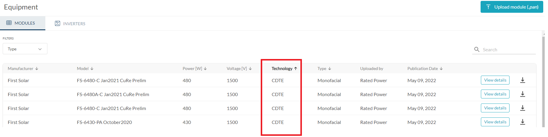
Check out our CdTe module catalogue in the Equipment tab.
In the Electrical tab, check out the new DC harness electrical configuration option.
DC harness cables look like the following image in RatedPower’s SLDs.
The list of possible inputs per harness will vary in number depending on the structure selected, the number of strings per structure and the string grouping configuration.
For any other questions or more information regarding this topic, you can contact us at: support@ratedpower.com