Remade design process, customized cables, thin film modules
pvDesign - backend v5.8.47, frontend v2.06
In May we released the biggest revision of the design process since the launch of pvDesign 2.0. The new version features an improved workflow, making the map and PV plant visualization the central element.
We also addressed one of the main complaints our users in the United States had, which was the possibility of uploading thin film modules. To release this feature, we also implemented the harness string configuration. Finally, it is now possible to customize the cable characteristics in-depth.
New Features
The following new features were released in May:
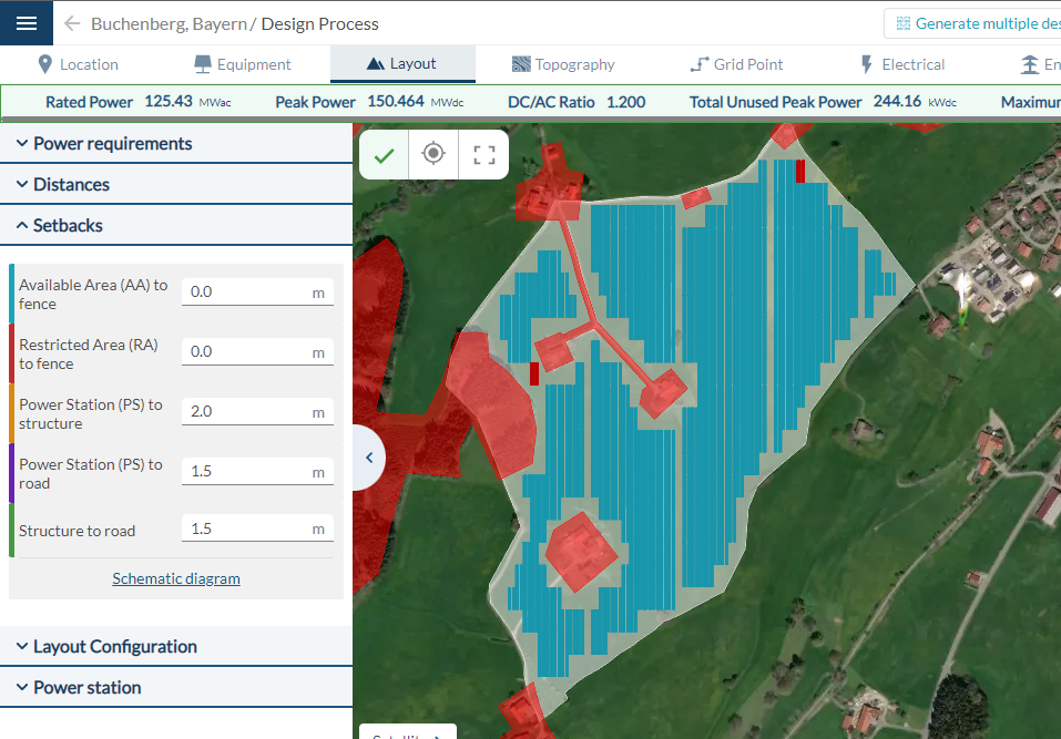
- Remade design process: The design process page has been completely remade. Now the map is always visible, so that users can iterate with any input. We also revised the position of many inputs to make the workflow easier to understand.
Find more information here.
- Customized cables: It is now possible to manually define the characteristics of the cables used in the PV plant. To do so, head over to the Electrical tab in the design process. Some of the editable properties are the cable conductor material, insulator, number of cores, and number of unified sections.
- Thin film modules: pvDesign can now simulate the energy production of PV plants using thin film (CdTe) modules. The calculation model now takes into account the spectral correction, and the recombination losses in the one diode model. You can find more information about the calculation model here. To use a thin film module, upload its .PAN file in the Equipment page. Find more information about how to simulate with thin film here.
- DC Harness: Alongside thin film modules, we released a new electrical system configuration. The DC harness configuration simplifies the connection of string cables to any collector, and is essential when designing plants with thin film modules due to the low number of modules per string. To enable the harness configuration, go to the Electrical tab in the design process.
- Definition of setbacks: It is now possible to customize the distance between certain elements of the PV plant, such as the distance from the area perimeter to the fence, or from the power stations to the structures. This new feature can be used to increase the fill factor of the PV plant, and to further improve the quality of the generated layouts.
- New map service: The web maps used by pvDesign in the design process and design results pages now use Mapbox as the service provider. This new service has better performance than Google Maps for the pvDesign use case, and will enable the development of exciting new features in the future. Additionally, it is now possible to manually change the map style.
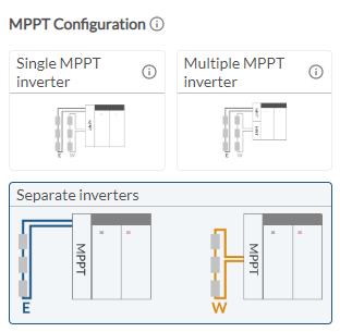
- New MPPT configuration for east-west structures: When an east-west structure is selected, users can now choose to connect each side of the structure to separate inverters (east side to an inverter, west side to another).
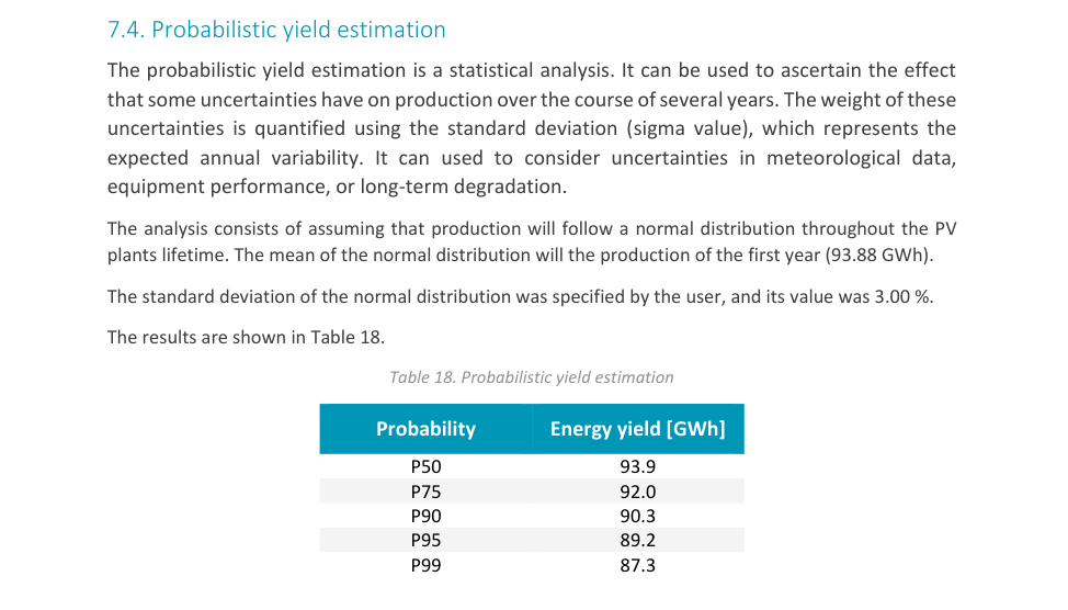
- Probabilistic yield estimation: The energy reports now display a probabilistic yield estimation, consisting of fitting a normal distribution to the production of the first year, with standard deviation defined by the user. The results can be found in the energy yield report, and energy yield results excel sheet. To modify the standard deviation (sigma), head over to the Energy tab in the design process.
- String box L2 configuration removed: We made the decision to remove the two-level string box electrical configuration in pvDesign. The reasoning behind this change was that the feature had very low usage, with less than one percent of all pvDesign simulations using this configuration. However, it was disproportionately impacting the development time of new features. The decision was made in order to speed up future developments.
Bug fixes and improvements
We also released the following bug fixes and minor improvements:
- Fixed an issue with the path of MV cables when there were intersecting shortcuts.
- Fixed the GCR calculation for east-west structures.
- Fixed a bug which was causing simulation failures due to the tracing of medium voltage lines.
- Fixed an issue which occurred when tracing the LV system in very thin gaps in defined RAs.
- Improved the positioning of LV collectors for 1V trackers.
- Fixed a bug in the LV SLD which caused the switchers to display an incorrect value.
- Fixed a bug in the LV system tracing when subareas touched each other in a single point.
- Fixed a bug in the LV collector positioning which occurred in border adaptation.
- Fixed a bug in the layout generation when using the harness configuration.
- Fixed a bug in structure placement when the available areas have inner holes.
- Fixed a bug in the MV tracing when using power stations outside the DC field and the pitch distance is large.
- Fixed a bug which caused the structure length value in the interface to be wrong.
- Improved performance for simulations with available areas which include inner holes.
- Improved LV string cable tracing in certain conditions, resulting in lower total cable length.
- Error messages are now shown in the login forms.
- The inputs in the topography tab now have minimum values.
- Fixed issues in the generate multiple designs form.
- Improved translation texts.
- Fixed a bug in the modules per string slider.
- Fixed an issue with the positioning of tooltips in the interface.
- Fixed connectivity errors in MV lines.
- Fixed a typo in the design results.
- Fixed the link to the tutorial