A newcomer or having issues defining your site? You have come to the right place!
To learn more on how to create sites directly inside RatedPower, check our How to create a site directly inside RatedPower article.
Basic Site Definition
1. Open Google Earth (desktop edition).
You can download Google Earth over here.
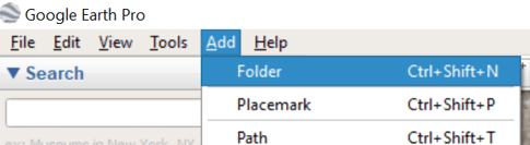
2. Create a folder inside Google Earth. All our site's elements will be defined inside this folder.
On the menu bar, go to: Add → Folder
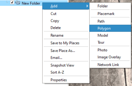
3. Using the polygon tool, let's start by defining our available areas, in other words, the areas where we would like to install our structures. Up to 30 different available areas can be defined. These must all be named "AA".
Right-click on the created folder and go to: Add → Polygon
Name all available areas as "AA". Do not number them or use a different name.
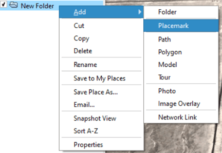
4. Using the placemark tool, define the road access point of each "AA" polygon. Each "AA" polygon requires its own road access point inside of it. All road access points must be named "AC".
Right-click on the created folder and go to: Add → Placemark
- Name the primary road access point of each AA as "AC". Do not number them or use a different name. (Optional: in case you want to define a secondary road access point, you need to name it "ACb". More on this below.)
- Always place each "AC" inside its respective "AA" polygon.
5. Now, using the polygon tool (Right-click on the created folder and go to: Add → Polygon), define the interconnection facility to the grid. You can choose between a substation (ST) and a switching and breaking station (SBS). Name the polygon according to your choice (either ST or SBS). In case you don't know where the interconnection facility is located, you can draw a random polygon near the PV plant.
Optional: more complex grid interconnection architectures are allowed (involving up to 3 levels of facilities). Check out this article to learn more.
6. Using the placemark tool (Right-click on the created folder and go to: Add → Placemark), we must define the medium voltage switchgear point inside the "ST" or "SBS" polygon. This point must be named "MV".
Please make sure to place the "MV" point inside the "ST" or "SBS" polygon.
7. The final step is to save the folder and not just one element inside it. This can be saved as either a KML or a KMZ.
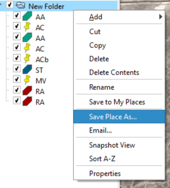
8. We can now upload the KML or KMZ file to RatedPower. Done!
Optional elements
- A secondary road access point. Each "AA" polygon can have a secondary road access point inside of it if needed. This has to be defined using the placemark tool and must be named "ACb".
- You can restrict areas so that no structures are installed in them. These must be defined using the polygon tool and must be named "RA". Up to 200 "RA" polygons can be defined in one site.
- You can also define road shortcuts that can help create more personalized pathways between the roads created by the software. More on this can be found in our How to create shortcuts in a site article.
- You can also create a custom medium voltage route on a site to connect different available areas between themselves or to the substation (ST) or switching and breaking station (SBS). More on this can be found in our How to create a custom MV route on a site article.
- You can fully customize the interconnection schema, deciding how to evacuate the power produced by the PV plant to the grid. This involves defining different interconnection facilities: switching and breaking stations (SBS), substation (ST) and pooling substation (ST) and how to connect them using either MV cables or OHL lines. More on this can be found in this article.
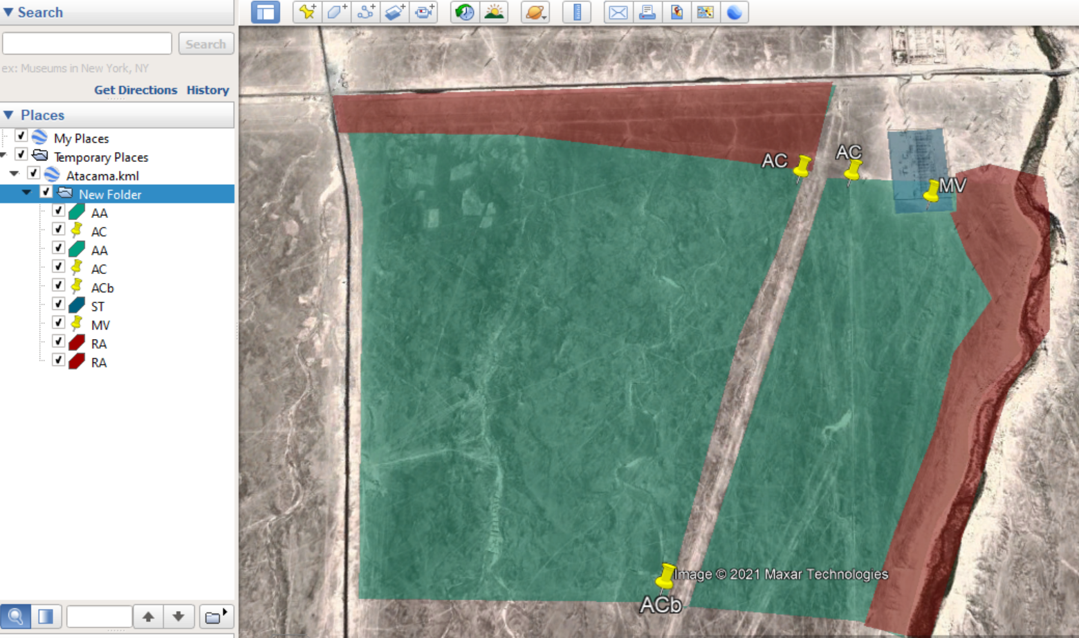
Your site may end up looking as follows:
For more information on some typical errors that users tend to commit, you can check our Basic Site Tutorial.
Advanced Site Definition
This section aims to offer some additional, more advanced tips on how to define a site.
Tip 1
RatedPower draws the final medium voltage line (the one going to the lowest voltage level facility) of each "AA" polygon from its "AC" point to the "MV" point located inside the "ST" or "SBS" polygon. In such cases, the "AC" point is acting as both the road access point and the medium voltage delivery point.
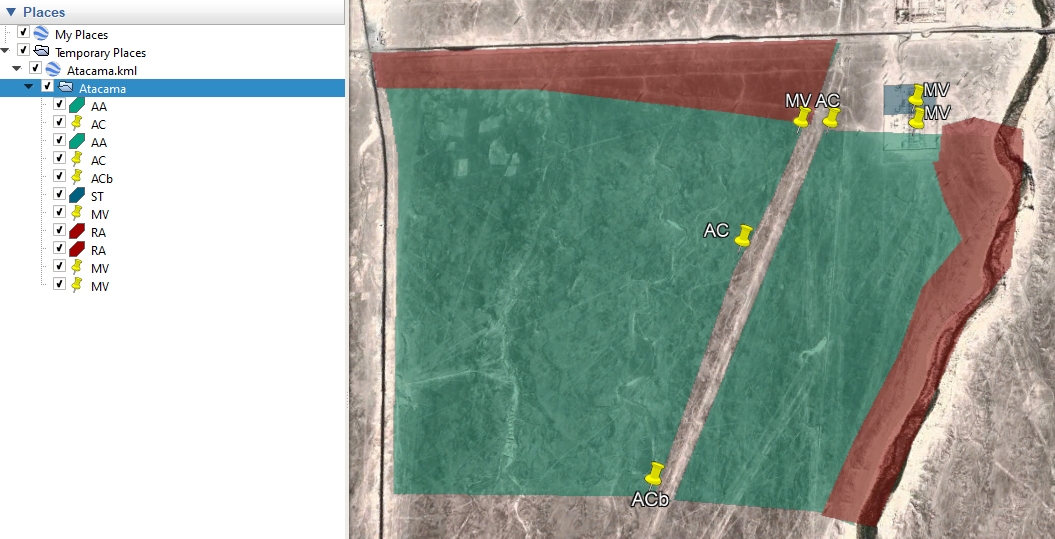
Let's say that we would like to separate the road access from the medium voltage delivery point. This can be done by defining an additional "MV" placemark inside the "AA" polygon. This way, the medium voltage line will go from the "MV" point of its respective "AA" polygon to the "MV" point of the "ST" or "SBS" polygon.
Your site may end up looking as follows:
Tip 2
As discussed in the basic site definition section, you can create up to 30 separate "AA" polygons where your structures will be installed. This, however, may cause some empty spaces in your power plant in case a certain power station does not fit in one of these areas.
An alternative and a much better way of doing this would be to create one big "AA" polygon that englobes all the areas that we need and then remove the unwanted parts by defining "RA" polygons. This way, a power station will be allowed to share structures between different parts of the whole PV plant and will thus achieve a greater total capacity.
Tips on How to Use Google Earth
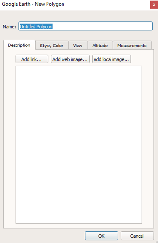
1. After you right-click on the created folder and go to Add → Polygon, a dialogue box like the one in the image below will appear. Make sure to create your polygon before closing this dialogue box. To create the polygon, left-click anywhere on the map and a point will be created. Create as many points as you need to define your area. Once done, click on the "OK" button.
2. In order to delete/eliminate a point while defining a polygon, simply right-click on the screen.
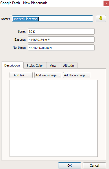
3. After you right-click on the created folder and go to Add → Placemark, a dialogue box like the one in the image below will appear. A placemark will also show up on the screen. Drag this placemark and place it where needed. Once done, click on the "OK" button.
For any other questions or more information regarding this topic, you can contact us at: support@ratedpower.com